LensRentals Cracks Open the Sony A7R, Gives Us a Peek at the Electronic Goods
Ever since we here at LensRentals first tested a Sony A7R, we were dying to take a look under the hood. Say what you will about Sony as a company, but they create some of the most elegantly-engineered camera bodies we’ve seen. Plus, the A7R is something of a groundbreaking camera, and we wanted to see how they crammed all that stuff into its little body.
The usual warnings apply:
- Do not try this at home. This post was made by semi-trained, semi-professional repair technicians who sort of know what they’re doing.
- The following blog post contains graphic images of the inside of a very nice camera. If such things make you squeamish, don’t read further.
- No cameras were harmed in the making of this blog post. The camera has been fully reassembled and is functioning normally.
But we were a bit afraid of what we were getting ourselves into. Because Sony engineers its cameras so efficiently, they tend to be difficult to disassemble, let alone reassemble. And Tyler, knowing us like he does, had probably set computerized alarms on the inventory control system, notifying him the instant an A7R got sent to the repair department for any reason. But Tyler was out sick for half a day — and there were actually some A7R bodies in stock. So we did what we had to do.
A Quick SLR Comparison
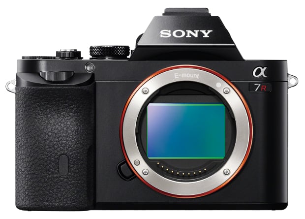
Mirrorless cameras tend to be simple and elegant compared to SLRs — in part, because they have a lot less stuff in them. Just to set the stage, let’s remove the body caps and compare the front of a Sony A7R with a Canon EOS 5D Mark II.
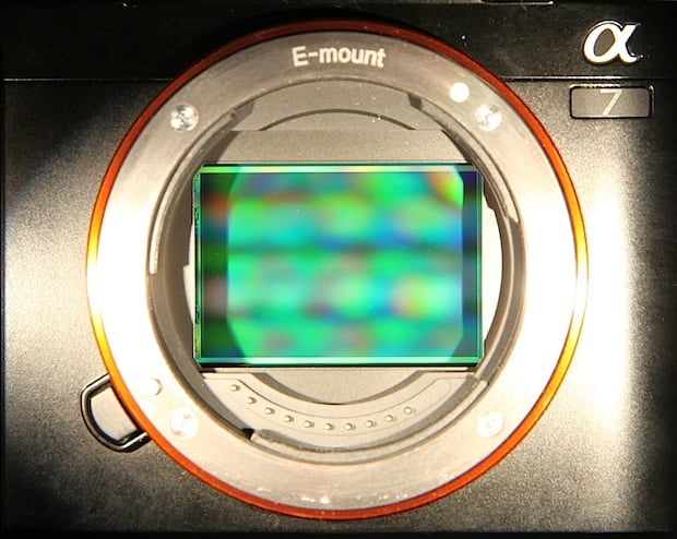
If you take the body cap off the A7R, here’s what you see:
Take the body cap off the 5D Mark II, and there’s a whole lot more to see:
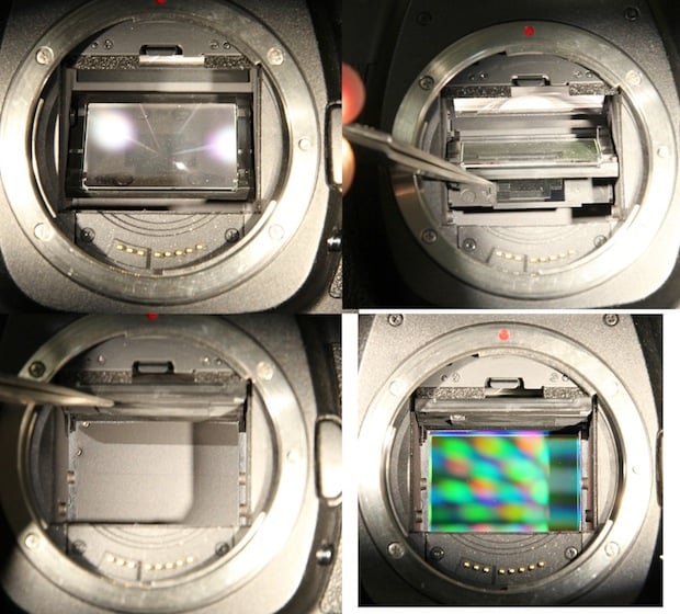
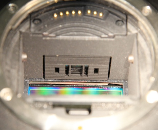
If you flip things around and look at the bottom of the mirror box, you can also see the phase-detection autofocus sensor:
This isn’t particularly important for today’s teardown, I’m just trying to show why a mirrorless camera can be simpler inside than an SLR ever could. If you’d like to compare this article to a teardown of an SLR, you might like our Nikon D7000 Teardown, or perhaps this teardown of a Sony NEX-3.
So Let’s Get To It!
As usual when we do these things, Aaron drives the screwdrivers, while I take the pictures and offer helpful comments or suggestions, like “Don’t tear that flex”. This teardown was a bit like Indiana Jones and the Temple of Doom, as we survived one near miss after another without quite destroying the camera. I’m sure my comments were most helpful.
The first trap we encountered was entirely of our own making. With almost every camera, you begin disassembly by peeling off the rubber grips to get to the screws beneath. Not with the A7R. The good news is that the A7R’s grips are completely bonded to the camera body, not held on with sticky tape, because there are no screws beneath them. They’re never going to come loose over time, unlike some cameras we know all too well. The bad news is that we found this out by spending half an hour trying to remove the unremovable grips.
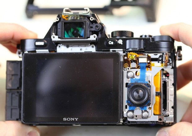
Once we gave up on grip removal and started taking out the screws we could see, things progressed quickly, and the back was off in no time.
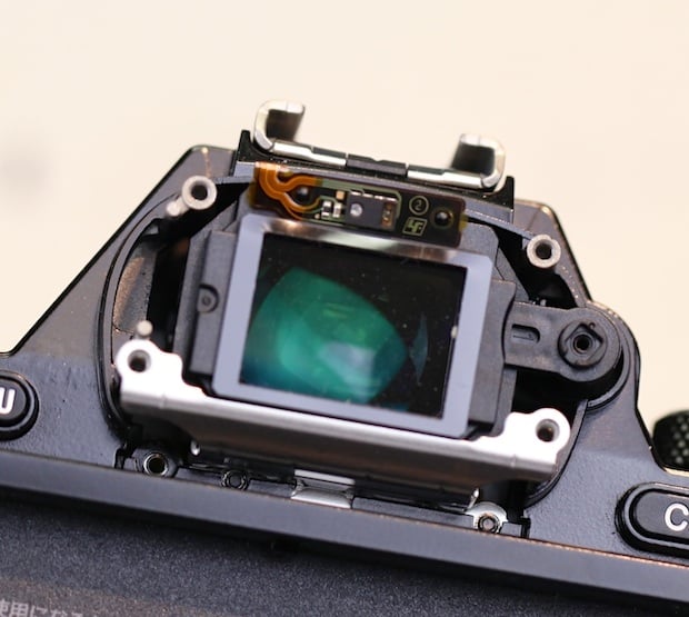
The electronic viewfinder cover came off just as easily. That’s the eye proximity sensor on the flex above the viewfinder:
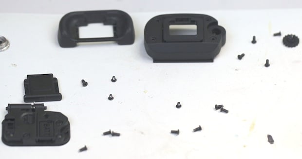
A very nice thing 00 and one that’s quite typical of Sony engineering — was that there were only two different screw sizes used thus far: one size for the casing, and another for the EVF cover. A typical Nikon or Canon camera has four to seven different screw sizes by this point.
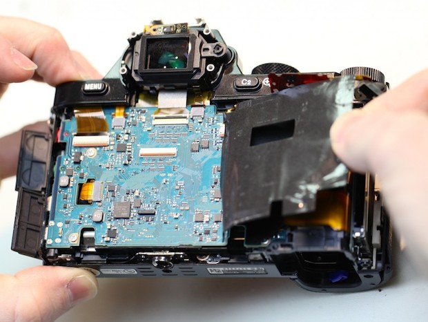
Back to the camera. With the back plate off, the LCD assembly is now exposed:
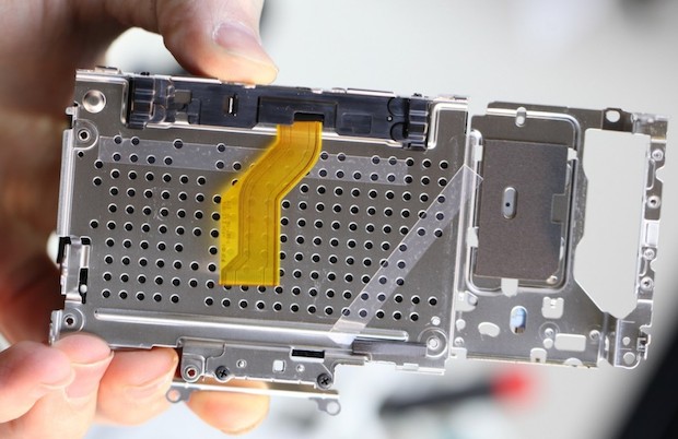
Removing a few more screws frees the LCD to be lifted up, showing the single large flex that connects it to the main PCB:
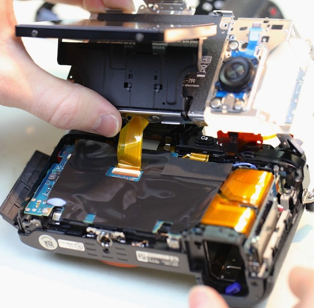
The LCD assembly is a very sturdy piece of metal that is totally rigid, even when taken out of the camera. That may seem inconsequential, but LCDs get pushed and pulled on quite a lot. When they’re weakly mounted, as we’ve seen on some very pricey DSLRs, they can get quite loose or even bent into the camera a bit:
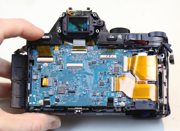
Near-doom adventure number two came as we started to peel back the thick shielding tape over the main PCB. On the right side, there are several flexes under the tape that badly wanted to tear themselves as it was removed:
But the tape came off without any major mishaps, showing a typically clean Sony layout. All flexes are arranged to have the shortest possible runs, with no wires winding across, around, or under the PCB as we see all too often in other brands.
There’s even a nice little cutout to let the PCB on the bottom left come up through the board, rather than making it 10 times longer so that it can wind around the edge from underneath:
The nice layout continued as we lifted up the large flexes on the right, showing smaller flexes laid neatly under the larger ones, rather than winding their way around them. The lower flex leads to the memory card slot:
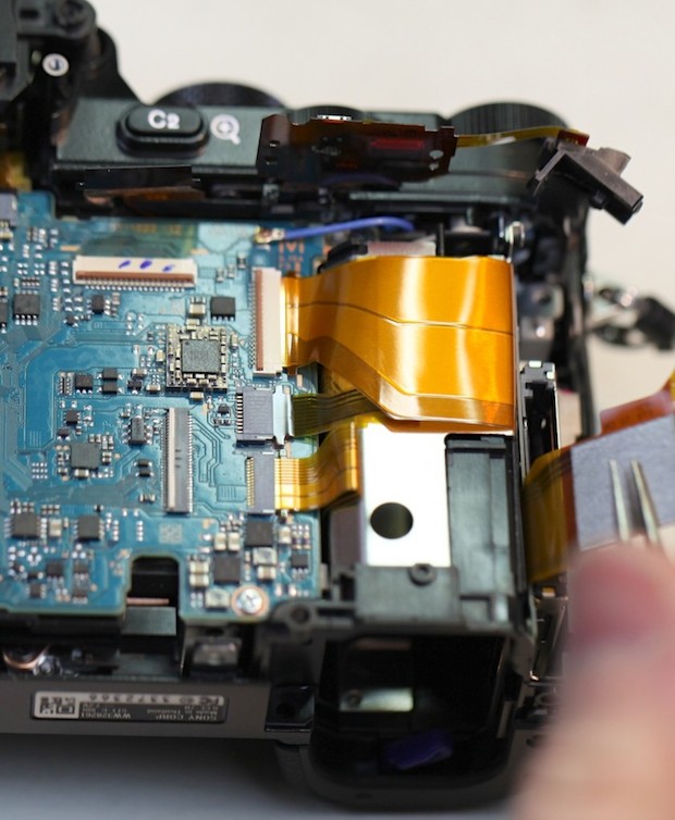
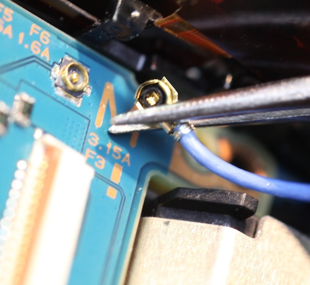
And a repair guy’s dream: That blue (I assume grounding) wire has a neat little snap connector, rather than being soldered to the board:
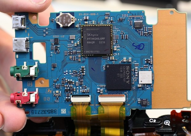
Disconnecting all the flexes lets us lift up the PCB, showing the input connectors and a couple more flexes coming in from underneath the board:
At this point, we thought we’d reached a dead end. The PCB was out, and so were all the screws, but neither the top nor the front would come off of the camera. We pried. We cursed. Finally, we realized that we’d been working so long that our caffeine levels were probably too low, so we went and had some coffee. And a snack.
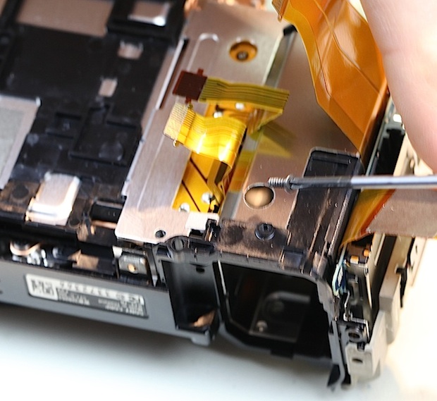
Once we came back, Aaron immediately discovered the Secret Screw of Sony, hidden away at the bottom of a hole in the right side of the camera:
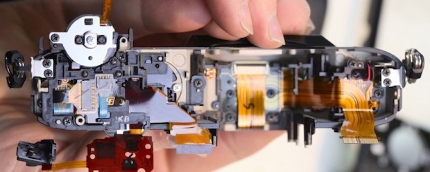
Once the Secret Screw was removed, the grip came off. With the grip off, the top came right off. And at last, the deepest secrets of the A7R were ours!
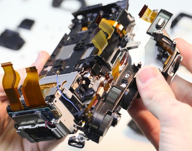
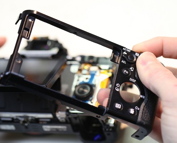
For completeness, here’s a picture of the top assembly. This can be disassembled further, but reassembling it is another matter. (This is why when you break a button on your camera, the repair is usually listed as ‘Replaced top assembly’. It’s cheaper to do that than it is to pay someone to spend hours reassembling the multiple flexes and buttons in the top assembly.)
The Nice Surprises
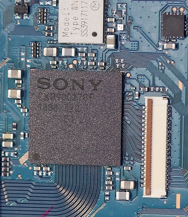
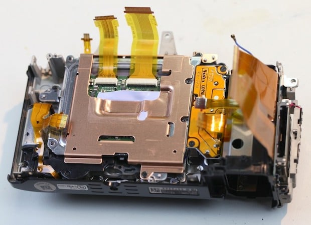
With our disassembly down to the core of the camera, things got even better. We had now exposed the back of that big, bad sensor, complete with heat sink tape and copper sink / shielding. (By the way, if you wondered who made the A7R’s shutter, now you know.)
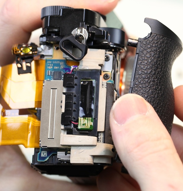
A couple more screws, and the sensor can be removed from the main mount of the camera, exposing the shutter:
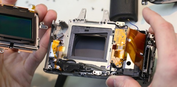
Note that the sensor doesn’t mount to the shutter. It mounts directly to the metal chassis of the camera, with shims in three locations to make sure that the sensor is properly aligned to the lens mount:
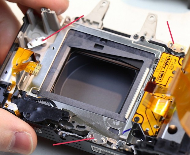
The simplicity of the design becomes easier to see with the shutter removed, and only the metal chassis of the camera left:
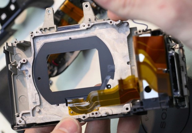
The sensor is mounted and shimmed on one side of the metal chassis, as indicated by the red arrow. The lens mount is attached directly to the other side, marked with a yellow arrow. There’s nothing else that needs to be calibrated or aligned:
Compare that to the pictures of DSLR mirror-boxes at the start of this article, where there’s a lens mount, two mirrors, an autofocus sensor, the main image sensor, and the focusing screen, each of which must be aligned and calibrated to the other.
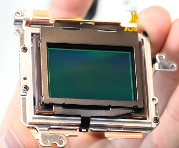
The Sensor
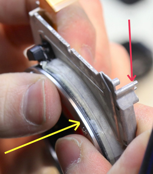
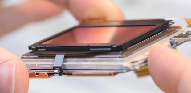
The sensor assembly is a nice, self-contained unit. One thing that was immediately apparent is that the cover glass on the sensor is held onto the assembly with three strong clips.
It does seem that — in theory, at least — replacing a scratched cover glass might be done without a complete sensor assembly replacement. Not to mention that there has been some discussion regarding removing or replacing the cover glass, possibly improving performance with adapted lenses in the process.
I can’t say for certain, but it appears this should be a simple matter. But the clips didn’t pop off easily and we’d already pushed our luck with this camera enough, so we decided not to force the issue.
One Last Image
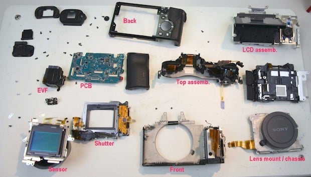
This is rather amazing. The completely disassembled Sony A7R consists of about a dozen major pieces, held together with 29 screws of just three different sizes. A typical DSLR has around 120 screws of 11 different sizes.
You might not care less about that, but do you know what I thought about? How much easier it will be to fix this camera when it breaks. How much simpler it must be to perform all the calibration that must be done during assembly. And how much simpler it must be to assemble the A7R in the first place. In other words, how much cheaper it must be to make this camera, than to make a DSLR.
About the author: Roger Cicala is the founder of LensRentals. This article was originally published here.