How I Made a 3D-Printed Film Movie Camera
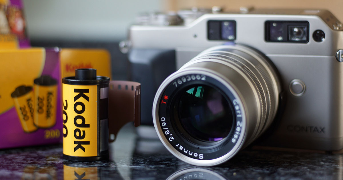
A couple of years ago I have been occasionally shooting 35mm films with point-and-shoot still cameras while also having the desire to shoot motion picture films.
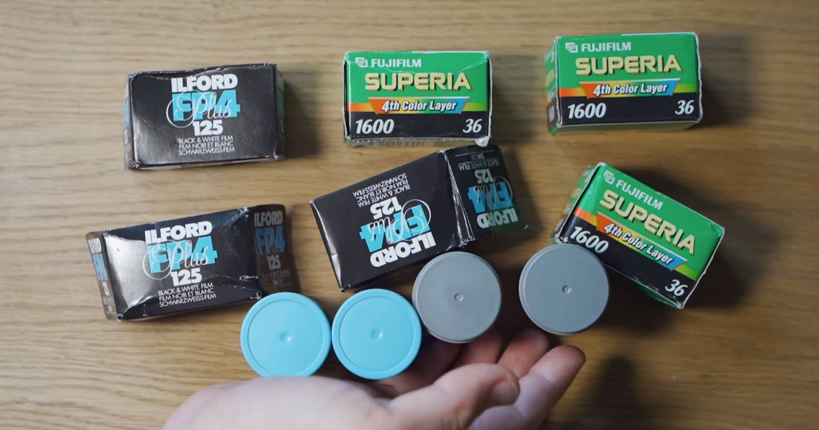
After researching, since I had some experience with 3D designing and printing, electronic design, and coding, I came up with the idea to build my own analog motion picture film camera. I’ve decided that my camera would utilize the standard 35mm film cartridges since these are cheaper and are widely available in much larger quantities and type varieties (B&W, Color, Reversal, UV, IR, special kinds …) and can be bulk loaded.
The main goal was to find an optimal balance between the number of frames, fitted on the cartridge and the size of the frame itself. Here I concluded, that the frame size should be the same as the Super8 format or larger. Other goals were an ergonomic and practical camera design, a good user interface with display, many useful functions, a completely automatic film feed/rewind mechanism, and some sort of developed film scanning ability. This would result in much more affordable and practical film shooting versus the Super8 format. And it’s way easier to home-develop 35mm film than Super8.
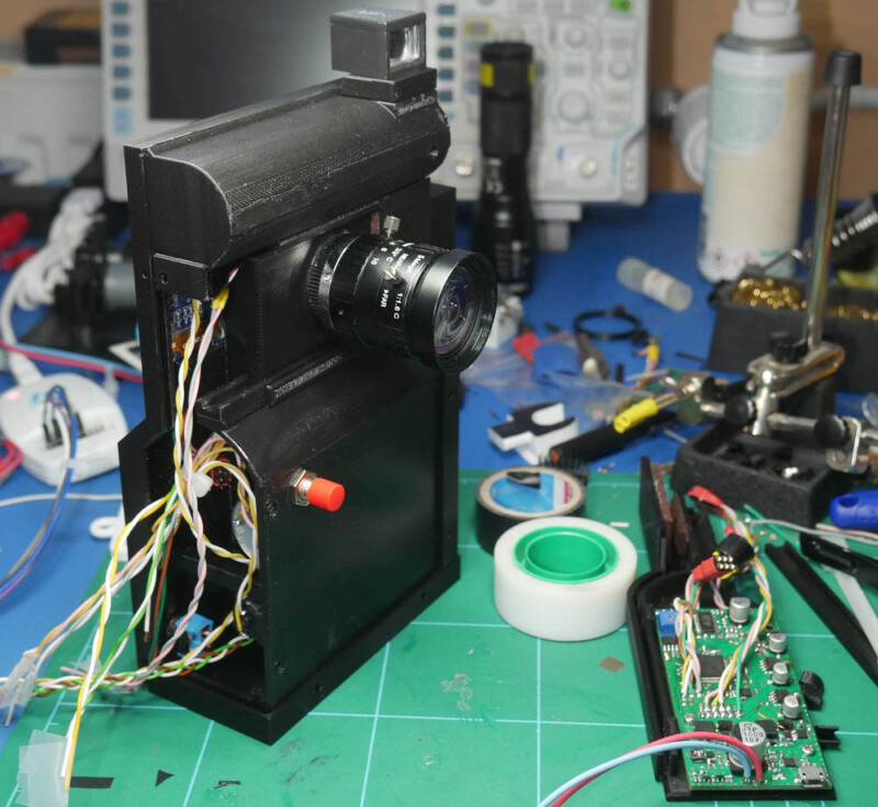
Internal Design and Construction
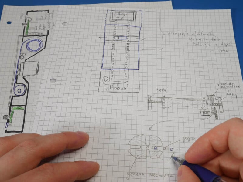
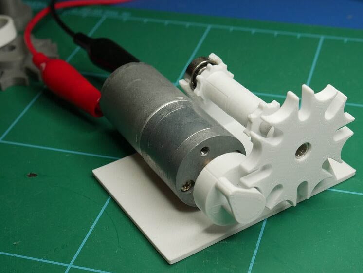
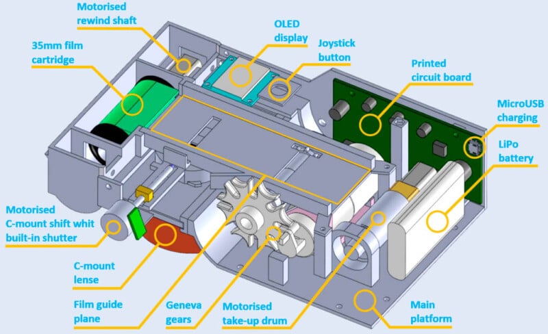
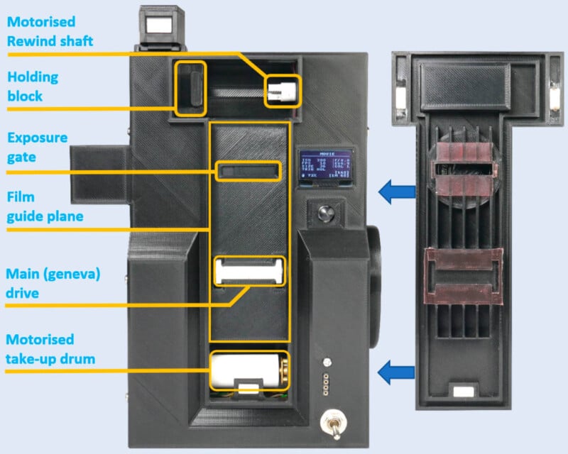
The basic internal camera design and its internal workings were firstly roughly sketched on paper. There I decided that the first thing to create would be some sort of intermittent mechanism for advancing the film during the blanking interval by one perforation hole. Here I have chosen the Geneva mechanism, which is capable of transforming a continuous rotational movement from a DC motor into an intermittent rotary motion on sprocket gears. A simple 8-position Geneva drive with sprocket gear on a basic platform was modeled on a computer and 3D printed. Using one full motor axis rotation, it moves the 35mm film by exactly one sprocket hole.

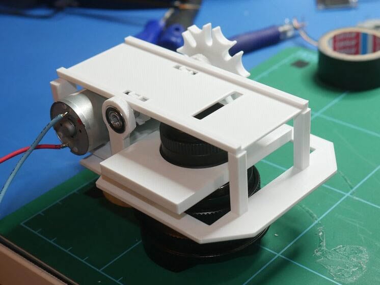
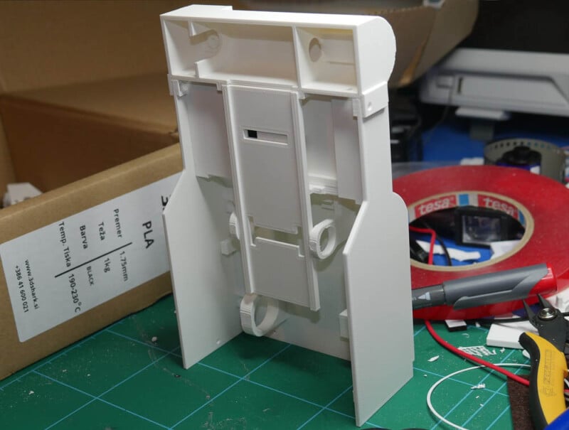
After successful testing, other components soon followed such as a guide plane for transporting film from a motorized 35mm cartridge holder to a take-up drum, a motorized C-mount shifter for selecting film track exposure with built-in solenoid light shutter, and room for a printed circuit board, a battery, and a display. Most of these components were held in place by the main platform, spacers, and screws. The intent was also for the camera to have a simple film-loading procedure, that doesn’t require any pre-slicing/combining or external reel film loading, just drop/load a standard 35mm cartridge and you are ready to go. For the lens I wanted support for interchangeable lenses, here was chosen the C-mount system due to its very wide option selection (from wide to telephoto), affordable prices and still being in production. Almost all components were 3D printed from black PLA plastic in order to block any outside light source.
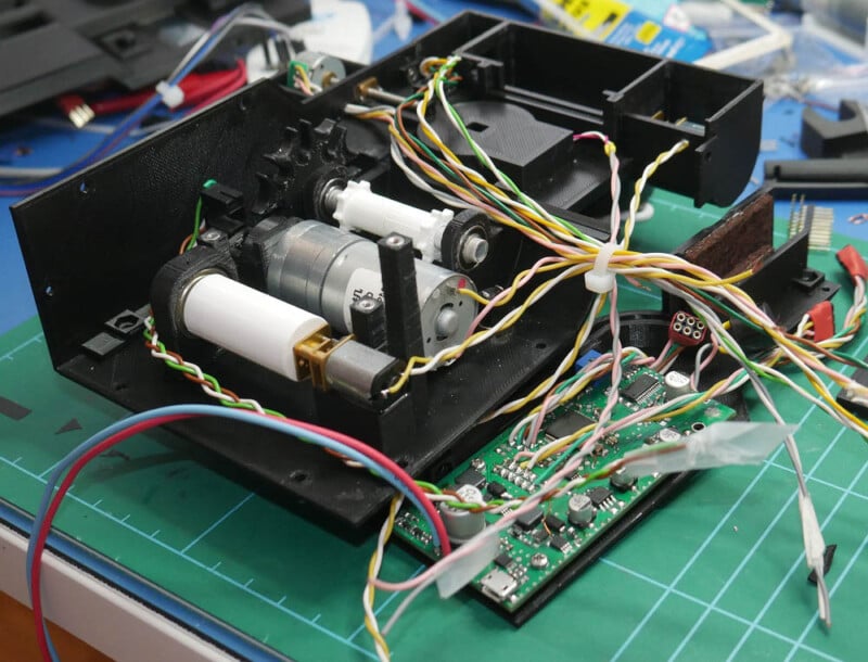
Regarding electronics, the plan was to make a single printed circuit board design containing all components with additional component expansion capability. An STM32F1 series microcontroller was chosen due to its large number of GPIO pins, a vast selection of different functions, and high-speed operation. The board was fitted with a power management system, motor driver chips for film transport and shutter control, a stepper driver chip for C-mount lens shift for track exposure selection, and a connection array for external sensors such as a light meter. All components are powered by an internal LiPo battery with charging capability.
The next task was coding. Its challenges were the creation of a user-friendly GUI with simple menu system navigation using a joystick button, four different modes of operation: Movie, Photo, TimeLapse, Scanner, and a system, that gathers and processes all data and displays it to the user such as measured exposure values, remaining recording time, current/saved settings, etc. Nearing the end of coding, many other useful features were added like a timer, recording button modes, and a visual/audible warning system. Programming was done in C language in the STM32 IDE environment.
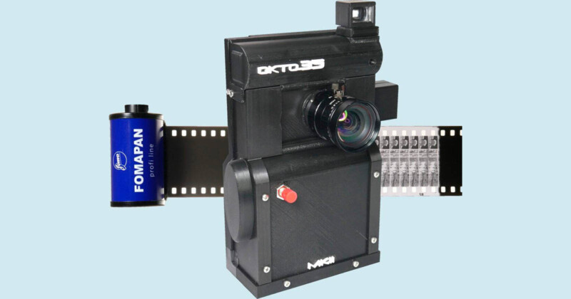
The last task was choosing a name for the camera. Among wide preselection, the name OKTO35 was chosen. ‘OKTO‘ is equivalent to the number 8 in the Greek language and refers to the Super8 format. ‘35‘ refers to the 35mm film format.
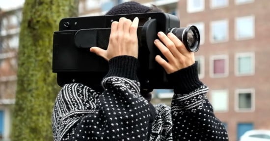
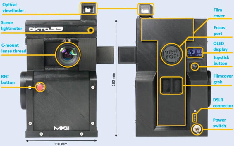
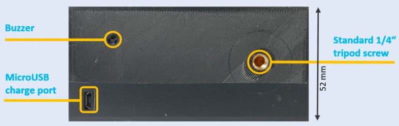
External Design
The goal of the external design was to be made simple and ergonomic. The walls were to be made from at least 2 mm thickness to ensure light tightness and structural stability. The front face features a hot shoe mount for a detachable optical viewfinder, a built-in scene light meter for lens f-stop adjustment, a C-mount lens thread, and a tactile recording button. With the back side, the user utilizes the viewfinder for scene preview, operates with OLED display GUI via the thumb joystick button, and has the access to film cover for film cartridge loading. The focus port is used for focus check and the DSLR connector is for sync scanning connection cable. At the bottom, we find a buzzer hole for audible timer/warning sounds, a standard 1/4” tripod mounting screw, and a micro USB port for charging.
Film Loading
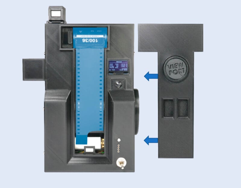
The film loading consists of a simple drop&load procedure. No pre-slicing, film combining, or any external reel loading is required. The film cartridge is placed between the motorized rewind shaft and the holding block. The film is extracted from the cartridge, placed down the film guide plane, past the exposure gate and the main drive, and attached to a motorized take-up drum. The film cover acts as a film pressure plate and sledge guide. It’s held down by strong neodymium magnets and the double wall seal design provides good light tightness. After loading, the film ISO and size settings are entered via GUI and film recording can begin.
GUI
The chosen display GUI structure idea was a simple 3-page system: Dashboard – Settings – General. Switching between main pages is done by the left/right joystick button action and page option selection with up/down action. OLED display technology was selected due to its good contrast and sun-readable capability.
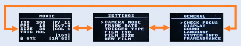
The content of both the Dashboard and Settings pages changes depending on the set Camera Mode option, which is the main feature of the camera. It enables a change of 4 different modes of operation: Movie, Photo, TimeLapse, and Scanner.
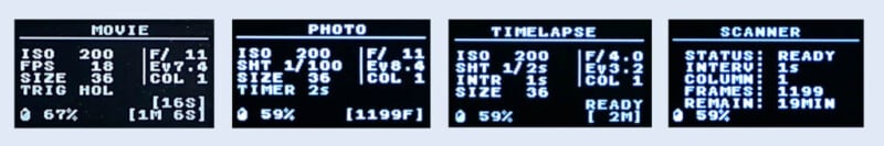
Movie mode enables the camera to be a normal recording camera with a main frames-per-second setting. Photo mode makes a still camera with a shutter speed setting, also useful for stop animation. TimeLapse mode is used for long interval exposures with the main interval setting. These three modes can be used interchangeably on the same film cartridge. The last mode is Scanner mode which changes the camera into a film-scanning device. Film cartridge, that was previously exposed and developed can now be reloaded back and scanned in the frame-by-frame method by front lens swap and using a DSLR or a mirrorless digital camera connected to a DSLR connector port.
All user settings and current film status are stored on built-in internal memory, which keeps it stored even in a battery under-voltage occurrence (flat battery).
The battery percentage status, calculated f-stop, and remaining film recording time or frame information are always present on the dashboard page. The camera also has other built-in functions such as a timer, recording button type, etc. GUI also features an advanced message system. It responds visually and audibly with warning or advice messages such as the end of the film, invalid setting, low battery, etc.
Camera Operation
The current camera design uses a standard 8 mm lens with manual f-stop and focus. The 8 mm approximates a 50 mm lens on a full-frame 35mm camera (close to human vision). The camera usage was made to be as user-friendly as possible. The intent was also to behave like a point&shoot camera with additional user settings. This was achieved besides the two manual settings: f-stop and focus, which are occasionally needed.
The manual focus is set once and doesn’t need to be set again unless a more close-up scene recording is required. Under normal operation, the current 8mm lens offers a focused range from about 1.2 m to infinity. If re-focusing is required, the user goes to the General page and enables the option “Check focus”. The lens shift motor sets the lens to the middle of the film and opens the shutter. The user then opens the viewport on the film cover and screws in a 25 mm lens. Due to the film’s partial transparency, the focus is checked on the film itself (as the focusing plane). When finished, the user closes the viewport and disables the option, resulting in the lens shift motor returning the lens to the previous track position.
Correct f-stop value is calculated by taking into account measuring current scene illuminance via a built-in scene light meter and setting film settings such as film ISO, fps, shutter speed, etc. The user points the camera to the desired scene via the optical viewfinder and presses the enter button, calculated lens f-stop is then refreshed instantly on the dashboard. The user then sets the lens f-stop according to the displayed value. If the scene illuminance doesn’t change much, the same lens f-stop setting can be used multiple times due to the film’s wide dynamic range.
When a new fresh film is loaded and the film specifications (ISO, size) are entered, the user has the option of three different modes of operation: Movie, Photo, and Timelapse. All three can be used interchangeably on the same film cartridge.
If the user selects Movie mode, an fps setting is taken into account and motion recording can begin. A time counter is displayed at the bottom showing the remaining track and total recording time in minutes and seconds.
Photo mode transforms the camera into a still camera, shooting frame-by-frame via presses of the recording button and with the shutter speed setting taken into account. This mode is useful for stop animation or just still photography. A frame counter is displayed at the bottom showing the remaining total number of frames.
Timelapse is used for long interval exposures with interval setting taken into account. User can select the timelapse duration and interval time and starts the recording process. A timer is displayed at the bottom showing the remaining time until the process is finished.
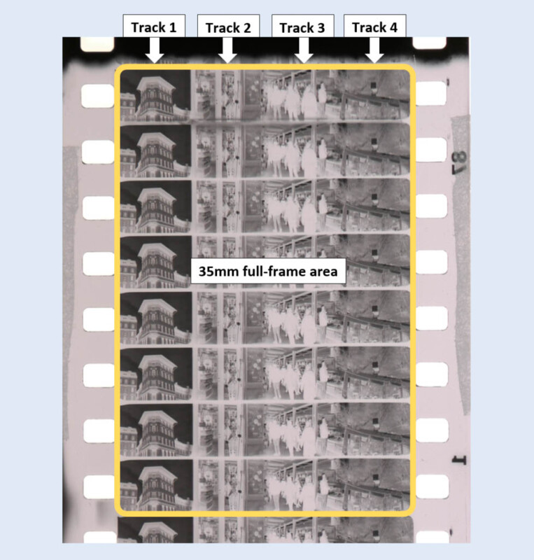
Frame Exposure Method
After some frame size and position math consideration I came up with the idea of moving film vertically through the camera and placing 1 frame per sprocket hole and 4 frames per useful width of the film edge to edge, effectively yielding 4 very long tracks in total of 1152 frames, which was later optimized to 1200 frames per one 36-exposure size 35mm cartridge. This method resulted in almost identical frame size compared to the Super8 format except for increased frame size. Compared to Super8 at 5.8×4.01 [mm], the new frame size is 6.3×4.73 [mm], effectively making the surface area increased by approximately +30% and diagonal size by +12%, which delivers smaller film grain and bigger/more detailed frames in traditional 1.33:1 aspect ratio.
Shooting Cost
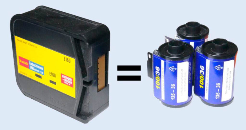
Using one standard 36-exposure size cartridge and shooting @18fps, we can obtain the recording time of 1 minute and 7 seconds. Comparing that to the Super8 standard 50ft cartridge’s recording time of 3 minutes and 20 seconds @18fps, three 36-exposure size cartridges are equal to one Super8 50ft cartridge in recording time.
The total cost for shooting 10 minutes of black-and-white footage at 18fps on Super8 is about $370/€330, and the total cost of doing the same on 35mm film (processed at home) is about $57/€51. So using black-and-white 35mm film instead of Super8 reduces the total cost by about 85%.
The total cost for shooting 10 minutes of color footage at 18fps on Super8 is about $370/€330, and the total cost of doing the same on 35mm film is about $108/€96. So using color 35mm film instead of Super8 reduces the total cost by about 70%.
Bulk loading makes these cartridges, even more, cheaper: with a black-and-white price of about $2.90/€2.60 per 35mm cartridge the total cost is about $34/€30 for a shooting time of 10 minutes @18fps. This brings the price down by about 91%.
Scanning Procedure
Most, if not all motion picture cameras only have a recording function. After exposure and development, a different and specialized machine is required or a lab service for scanning purposes.
This camera is designed in such a way, that also serves as a developed film scanner with a few additional parts. The scanning procedure starts with loading the developed film cartridge back into the camera, replacing the front C-mount 8 mm lens with a 25 mm lens in order to correct the field-of-view, and opening the Viewport. A change of camera mode is performed via GUI into the Scanner mode. Here the user can set the scanning interval length. This puts the camera into scanner ready state.
The user then utilizes a DSLR or mirrorless camera for lens-to-lens image transfer (usage of a smartphone camera with a wireless connection method will be possible in the next camera version MK III). For film backlight sources through Viewport, a common LED desk lamp will suffice. The lens focus, zoom, and F-stop adjustments are made in order to obtain the best image quality. The last task is to connect the DSLR or mirrorless to the camera using a common DSLR 2.5mm connector cable. Usage of stop motion animation mode in the DSLR or mirrorless camera produces video, made up from all scanned frames.
Scanning is started and performed automatically one track at a time using the frame-by-frame method in order to obtain the best flicker-free image quality. Meanwhile, the display Dashboard page provides useful information regarding track number, remaining frames, and scanning time (it takes about 25 minutes per 35mm 36-exp cartridge). When the scanning is completed, the user is notified and a new film can be scanned.
Camera Features
- C-mount lens support
- 4 function modes: Movie, Photo, Timelapse, and Scanning
- Fully motorized and automated film wind/rewind and film exposure track shift
- Built-in scene light meter for F-stop exposure calculation
- Bright and sun readable 128×64 1-inch OLED display with user-friendly GUI
- Simple and ergonomic thumb joystick button GUI control
- Built-in large capacity LiPo battery with charging capability
- Built-in buzzer for audible timer and warning sounds
- Detachable and adaptable optical viewfinder
- The movie frame rate can be set from 10 to 24 frames/second with a common 180° shutter speed
- Photo shutter speed ranges from bulb mode to 1/100s with a settable timer
- Timelapse interval ranges from 1 to 6 seconds with a common 180° shutter speed
- Supports wide film ISO range from 50 to 3200
- The camera can use multiple standard 35mm cartridge sizes of 12, 24, and 36 exposures
- Supports negative and reversal black&white, color, UV, and IR films
- Ergonomic and intuitive external design
- Responsive system due to the fast STM32F1 series processor
- Magnetically sealed film cover for easy cartridge loading and good light-tightness
- Self-cleaning film cartridge design for dust reduction during recording and scanning
- Film cover sledge guide design for scratch reduction during film transport
Thank you for checking out the project!
About the author: Blaž Semprimožnik is an electronics engineer and amateur coder based in Slovenia. You can find more of his work on his website. This article was also published here.