How to Record Electrical Discharges with a Digital Camera
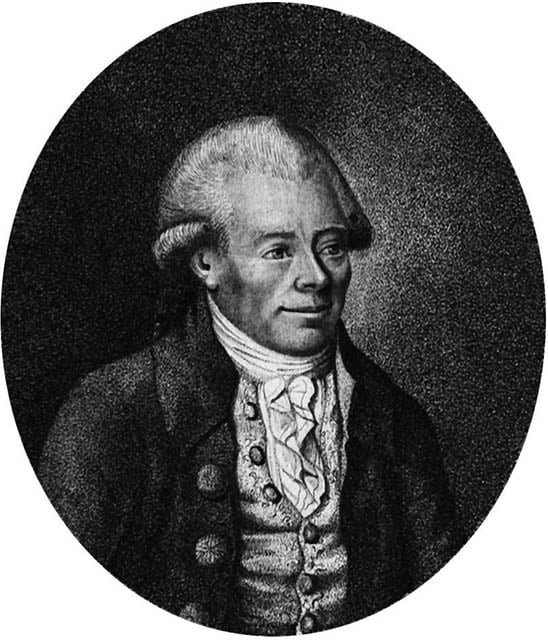
The recording of the patterns made by static electricity date back to the invention of the technique in 1777 by Georg Lichtenberg. Since he was the first to observe the patterns they are referred to as Lichtenberg figures.
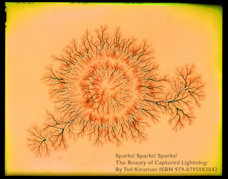
I first became interested in trying my hand at recording sparks when I noticed some intriguing static discharges recorded on old X-ray films. I knew that these patterns were sometimes captured on film as a result of static electricity, but I had no idea that they had such a rich history and played a significant role in the understanding of electricity. By 2008, I had conducted some promising experiments with X-ray film. In 2018, I finally found the time to write a short article.
In the fall of 2018, while attending a conference in Holland, I had the opportunity to visit the Teyler Museum. During a tour, I learned about the museum’s significant contribution to the study of electrical spark patterns, thanks to the installation of a giant electrostatic machine in December 1784. I was in awe of the immense electrostatic generator, towering over two meters in height. In one corner of the room, I noticed original copper etchings showcasing Lichtenberg patterns created by the giant electrostatic machine’s molten pitch. I made a mental note to revisit my project of recording electrical patterns using both film and a digital camera.
Lichtenberg figures are created within billionths of a second (nanoseconds) when air or a plastic undergoes a dielectric breakdown that allows high voltage to pass through a material. This process is desired to make an air-gap high-speed photographic flash work. The understanding of this process allows ultra-fast air-gap flashes to operate. These types of flashes are used for high-speed applications like capturing a bullet in flight.
The creation of a Lichtenberg figure happens when a high-voltage pulse is in contact with a material. Most often the material in contact with the high-voltage pulse is an insulator under room conditions. If the distance between the high voltage and the ground is short enough, the electricity will ionize the air and turn the air into a conductive plasma. The conductive plasma will allow electricity to travel.
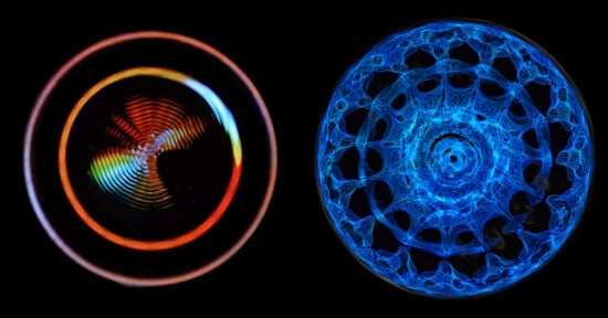
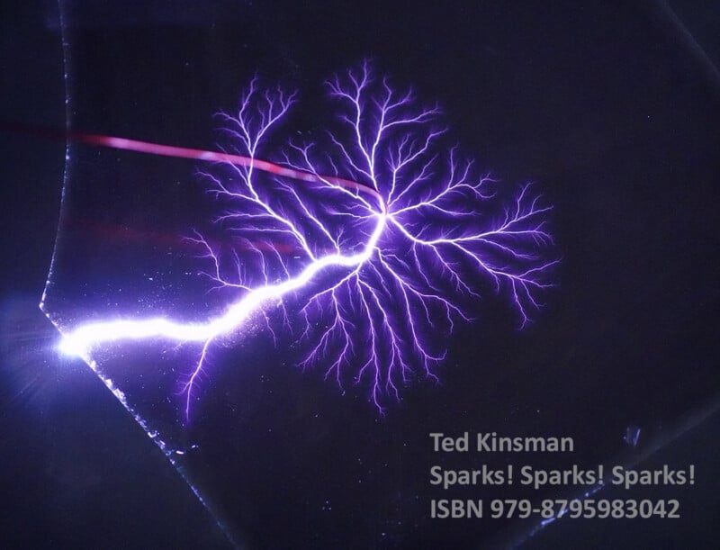
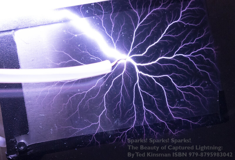
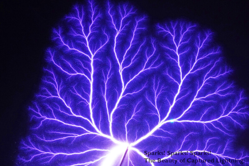
As the electricity travels in the air, the air continues to heat up. Too much electricity and the air will get so hot it will expand faster than the speed of sound and make a loud noise. This is the process by which lightning creates thunder, but on a larger scale. The images here are records of the heated air (plasma) giving off light. The light can come from air alone, or from an air-material surface. The surface effects of different materials yield differently shaped Lichtenberg figures of different colors. The figures are dependent on the conduction, material capacitance, the strength of the electric field, and several other factors:
In conventional electrical circuits, charge moves from the positive to the negative potentials of a circuit. This notation is left over from the days before the discovery of the electron. We now know that the electron is the mobile charge and is responsible for the flow of energy. In reality, the high voltage positive spark creates a drain for the electrons in the film. The electrons flow together as fast as they can. It turns out that the flow of electrons and the resulting corona discharge is incredibly fast and will make a Lichtenberg pattern in hundreds of nanoseconds.
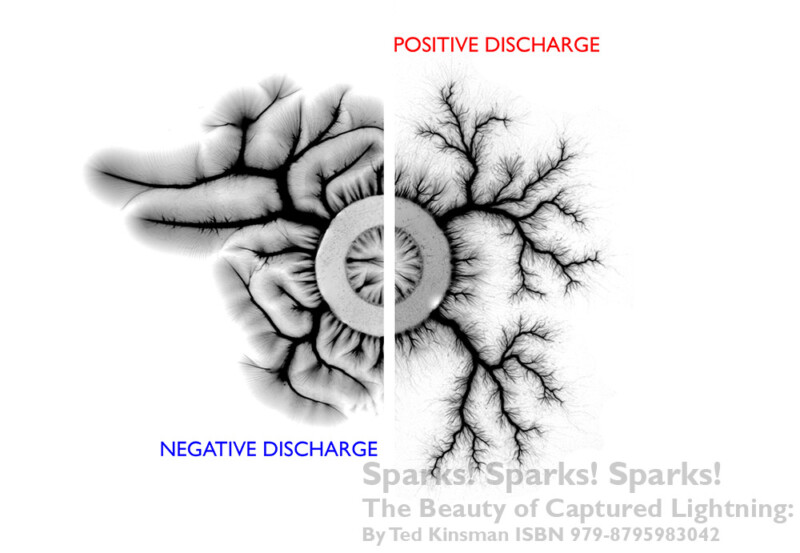
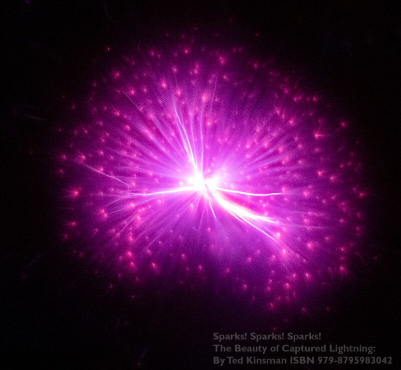
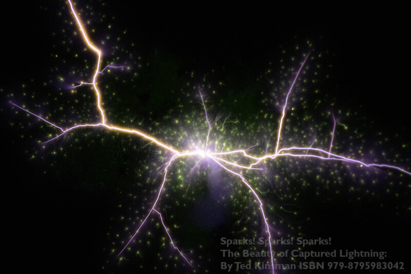
Positives Spark discharges do look different from negative spark discharges. We now know that the film material is a source of electrons for a positive charge (that is the electrons in the film will move to the positive electrode). The negative spark is a source of electrons that will flow out across the surface of the film. A fresh sheet of film placed in a grounded experiment will yield the characteristic patterns every time. The results of experiments are not clear when a residual unknown charge has built up on the film. The results are often a mix of positive and negative discharges. I find these experiments to yield particularly beautiful and surprising results.
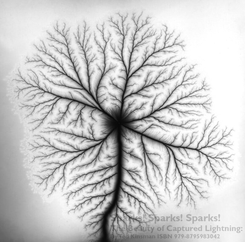
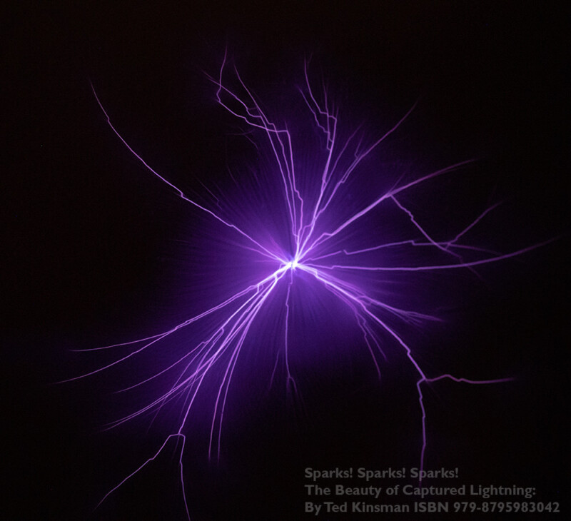
The majority of the time I photograph positive discharges since I like the looks of them better.
The Van de Graaff Generator
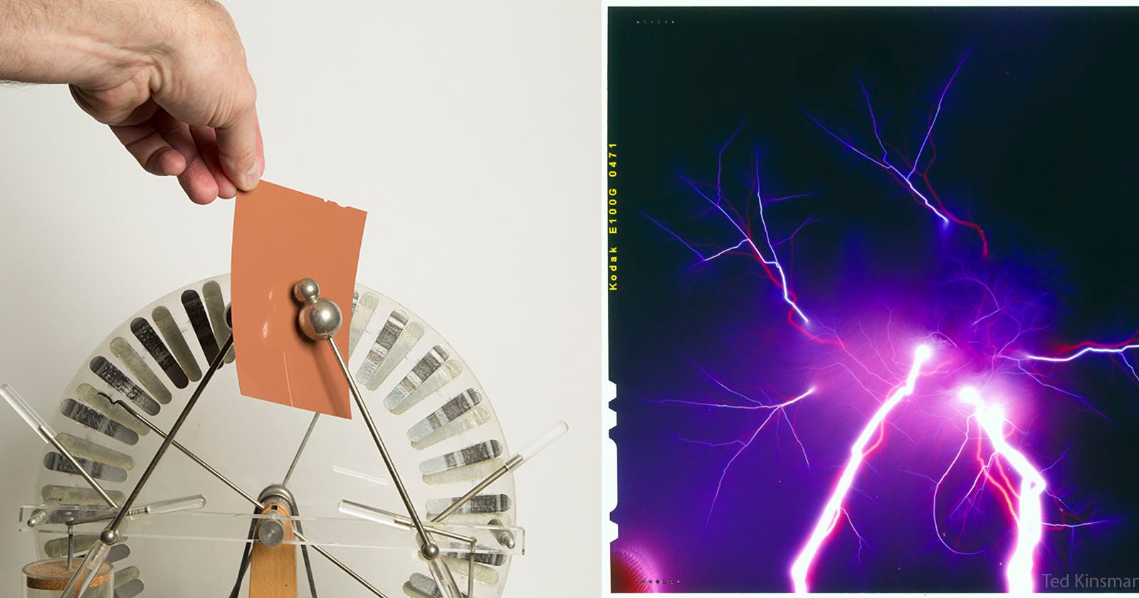
This device was invented in 1929, by physicist Robert J. Van de Graaff at Princeton University. The construction of the device is relatively simple, as a plastic belt moves around two pulleys of different materials. A positive charge is carried from the bottom and deposited on the top sphere. The area of the sphere is important since the top sphere acts as a charge storage device or a capacitor.
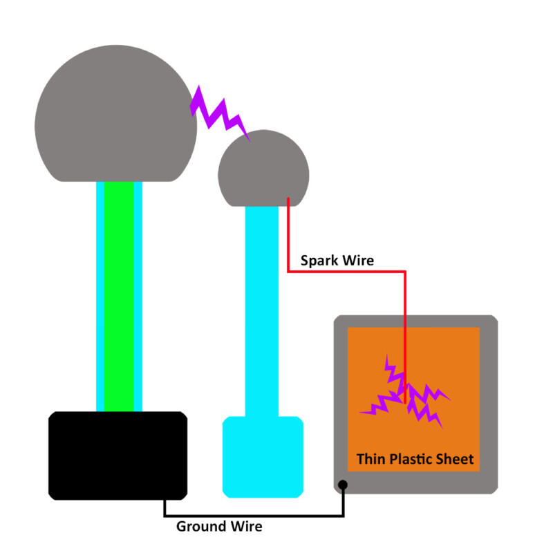
In this setup, a second sphere is placed near the Van de Graaff sphere and acts as a spark gap for the experiment. The second sphere supplies the positive charge to the film. This setup gives very consistent and repeatable results and a Van de Graaff generator is relatively safe for experiments as long as the design is not modified by increasing the size of the sphere or attaching external capacitors.
The base of the Van de Graaff generator acts as a ground and the conductive base under the film is connected to this point as the reference ground for the experiment.
As the generator is run the distance between the spheres (A and B) is adjusted to trigger a spark at the desired voltage. The distance S for the spark is the distance that is adjusted. A 30,000-volt spark will jump 1 centimeter. The sphere A of the Van de Graaff holds the charge and acts like a capacitor. The larger the surface area of the sphere the more charge and the higher the current of the triggered spark. It is a good idea to not modify any supplied equipment due to safety issues. The spark will travel along wire C and discharge on the emulsion side of the film. The film is placed on top of a conductive aluminum this test setup shows the spark traveling on a thick sheet of Mylar, placed on top of a grounded aluminum sheet.
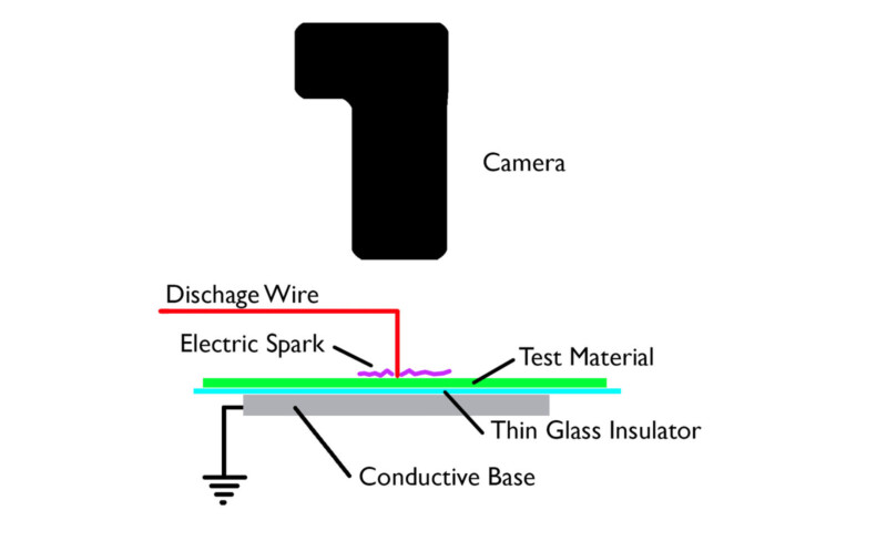
To simplify the use of a digital camera, I use a thin bent discharge wire and photograph the discharge directly. If the test material is a non-conductor (like film) the layer of glass can be left out. I have found that sheets of mica create some unique patterns, as does different types and thickness of glass.
The thinner the con-conductive layer of glass the stronger the electric field created and the better the electrical discharge pattern.
A thin wire is placed on the test material and is used for the spark discharge. The camera is placed directly over the subject or to the side. This technique works well for opaque materials as long as there is no possibility for the spark to travel below the surface. If fluorescent paper is used in this application the spark can travel below the paper and not be seen by the camera.
Of course, this technique is open to a lot of experiments. Since the high-voltage spark gives off a lot of UV light, fluorescent paper can be used to capture this light and increase the amount of light the camera can record.
Transparent electrodes can be made from salt water, and numerous other configurations can be invented. Last of all – do not forget the sparks can be recorded in film.
P.S. For more information, have a look at my recent book outlining this experiment and numerous others.
About the author: Ted Kinsman is a Professor of Photographic Sciences at the Rochester Institute of Technology (RIT) where he teaches technical imaging. He has contributed to numerous articles, books, and movies, including South Park, SpongeBob SquarePants, and the Planet Earth Series. In 2019, he was the recipient of The Louis Schmidt Award for lifetime achievement in science imaging from the Bio-Communications Association (BCA). He is the author of Cannabis: Marijuana under the Microscope. His most recent book is Sparks! Sparks! Sparks! The Beauty of Captured Lightning: Documenting Lichtenberg Figures of Electricity with Film and Digital Photography. His current research focuses on Reflectance Transformation Imaging (RTI) and Light Sheet Microscopy.