How to Make an Auto 35mm Film Scanner with Arduino Nano and Python
Waiting while flatbed scanners scan a color negative film is nothing to be excited about. This process and the subsequent color precorrection can take anywhere from an hour to two.
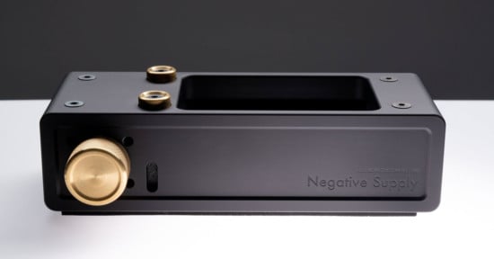
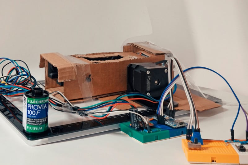
A typical digital camera scanning setup includes a digital camera, a tripod (or a copy stand), and a film carrier. Among the 3, I would imagine the most scarce item is the film carrier. Luckily companies such as Negative Supply started to make these much-needed film carriers. But these can also be rather expensive. Luckily, any DIY film carrier made out from cardboard that is able to push and pull an uncut 135 format (35mm) film via a simple shaft system will work great. More on that later!
A bit of background. Right off the bat, I should say that I am not affiliated with Negative Supply, Capture One, or Negative Lab Pro. I happen to own their products, and I happen to like using them (for now). Before, I was operating the venerable Epson V600 for scanning films. This was very nice as it enabled me to scan my own films, but the speed wasn’t there. Moreover, I was not completely enjoying the grains I was getting.
Having said that, my reasons for why I decided to make this project is more multifaceted. I enjoy supporting the film community and film-centric companies like Negative Supply, Lomography, and Negative Lab Pro. I also like the idea of slightly jolting the DIY community toward this niche domain. Lastly, I also really wanted to program a microcontroller for the first time. Taking up this project has thought me so many things. I admit, only a month ago, I couldn’t tell the difference between an Arduino and a Raspberry Pi.
After randomly settling on an Arduino, mostly because of its price point, I needed to find a problem to solve.
This did NOT take very long! I first fixed my UniRoller developer issue, which was a result of using a JOBO expert tank 3010. And then I focused on automatically watering my tomato plants for the times I went on a hike. And my final and current project was to fix this issue I had with scanning films. This also gave me the excuse to practice some Python programming.
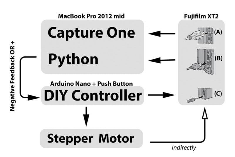
As of today, I have now completed 2 separate film scanning programs. One written in Python language, and the other one written in C++ (also referred to as an Arduino sketch). They both use the same hardware, but there are major differences in how they function. One is enabled by Python computer vision and is fully autonomous (automated positioning, picture taking, and moving to the next frame). The other only mechanizes the film progression. The user makes the necessary corrections in film position and then takes the picture using the controller buttons.
To implement this project knowing Python (C/C++ for Arduino) would be ideal, but it is not necessary for clicking the run button on a browser that runs Jupyter Notebook (found in Anaconda). That said, the user is required to download Python and 4 libraries. I highly suggest the Anaconda bundle as it is a one-shop solution, with a very rich online community.
After this installation, Python libraries, Numpy, pyFirmata, SciPy, and cv2 are also required. You can install these Python libraries using the Anaconda-Navigator or PIP install em from the terminal. The internet is littered with how-to tutorials on this. Having said that, I have used the Jupyter web interface for making and running the Python code. These programs will have an ipynb extension. However, it would be best to start by installing the Arduino IDE, as this is where it all starts (Arduino scripts have a .ino extension). There will be more details on this later.
Ok, lets move on to the actual awesome Setup:
Let’s see this setup in action!
Mode 1: Arduino only and using manually correcting position:
Mode 2: Automatic correction with Python:
Mode 3: Arduino plus Python in action on a DIY cardboard film carrier:
If Python and automation is not your cup of tea, but you still want a stepper motor to drive your film. You can also find a dedicated Arduino sketch on the Github site. I like this code as it is extremely simple to use and once uploaded to the microprocessor, using the Arduino IDE app, one would never need to see a computer script, plus it’s a tad faster, which is really convenient.
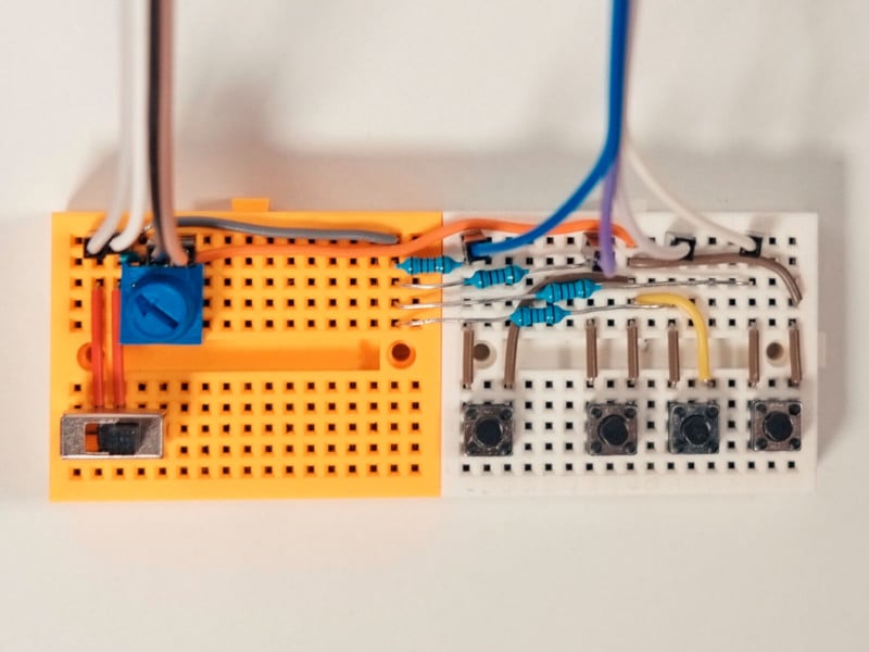
Here, the micro corrections to left and right are made using the dedicated buttons (the middle two in Figure 5). The button to the most left is the shutter release button, and the most right is to progress to the next frame. This setup should work on Fujifilm and Canon cameras. That is because the shutter release cable I once owned was Canon-branded and I tried to imitate the voltage values I read from it. Please bear in mind that there are risks associated with connecting external circuitry to your camera. Please attempt this DIY setup at your own risk.
What does a microcontroller do?
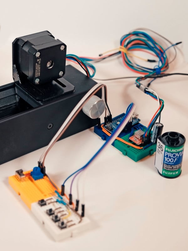
Firstly, the microcontroller used here is called the Arduino Nano. There are a gazillion YouTube videos of DIYists using this board. Essential a microcontroller is an integrated circuit (a chip that has many many discrete electrical components) that uses discrete voltage (3.3V or 5V) in order to say yes (in computer terms equals to 1, True, etc.) or 0V for saying no (0, False, etc.). There is also a grey zone in between where it’s not good, but I don’t know the details at this time. It communicates using its pins that are located on its side.
These pins can also read voltages too. Pins that read and write 1s and 0s are called digital pin and are denoted by D. Some of the D pins can also modulate pulse over time. This is denoted by PWM or ~. And some pins can read analog signals which are denoted by A. These are not 1s or 0s. They typically read a range of 0-1000 on an Arduino board, and this is how we input the desired speed of the stepper motor. The pin layout of the microcontrollers is available on the internet. So when wiring your circuit please take care of the wiring. Also, do not power your board while wiring.
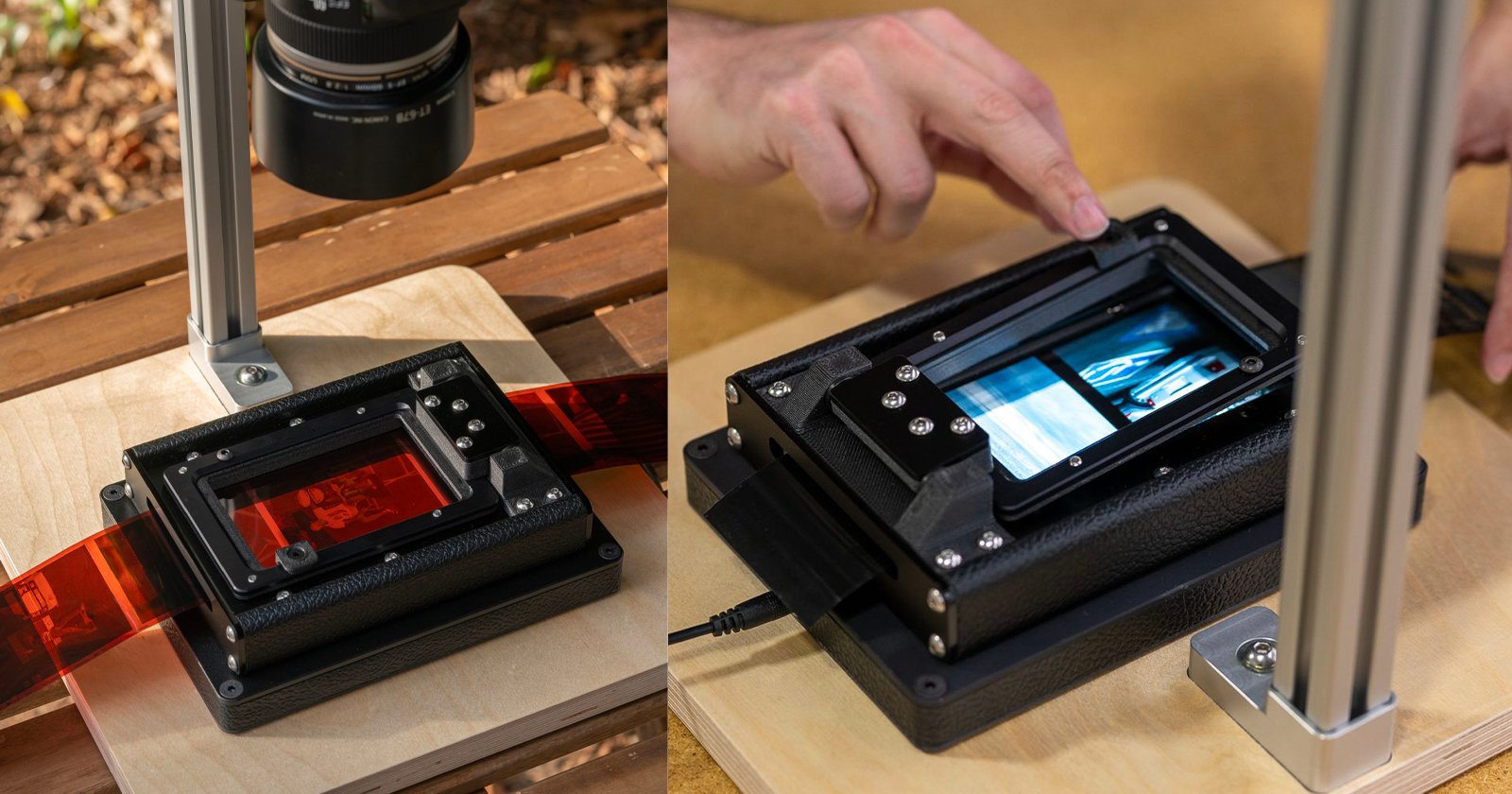
Correcting film position using Python.
In order to correct the position of the film, Python requires feedback. To do this we utilize the Video Capture Card HDMI to USB 1080p (item 4).
By perfectly positioning the film on the film carrier, maximum camera sensor resolution is achieved for every 35mm frame.
When maximum resolution is paired with a good macro lens, the grains can be a joy to look at. To active this, edges between frames are determined, and this information is used during the correction phase. This means that if we have a 24-megapixel sensor like we do in Fujifilm X-T2, our scans will almost have a 4000 by 6000 pixels per image. To position the frame perfectly our Python program only requires a 100p resolution. Therefore, the 1080p video capture is downsized in Python. However, a full 1080p video streaming with the card would make an excellent WebCam over Skype, Zoom, etc.
The current version of the Python program will not work with color positive films.
I have only been part-time working on this project since this past August. I am hoping to update the program in the near future for color positive film rolls. Next time I have an uncut positive film roll, I will take a weekend time to make this happen.
This is an open-source project subjected to MIT open source license. Which means that it is free to distribute, change, and use. In turn, the software for detecting frames could drastically get better with new and fancy algorithms over time. I highly encourage fellow Python programmers and data scientists to fork the project from my Github and showcase their talents.
I intended this page to be understood by people who are just starting off their journey into the world of microcontrollers. Thus, if you have a question or have a suggestion please don’t hesitate to share them.
Lets start making our scanning machine:
Outline
1. Mounting the Stepper motor and making a new shaft
2. The controller
3. Starting with the Arduino Nano (Blue) and the Stepper Motor board (RED)
4. The wiring
5. Downloading from Github and getting started
6. Items used and costs
1. Mounting the Stepper Motor and Making a New Shaft
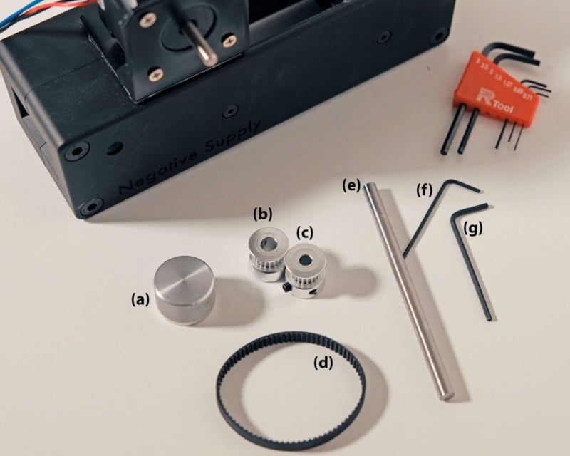
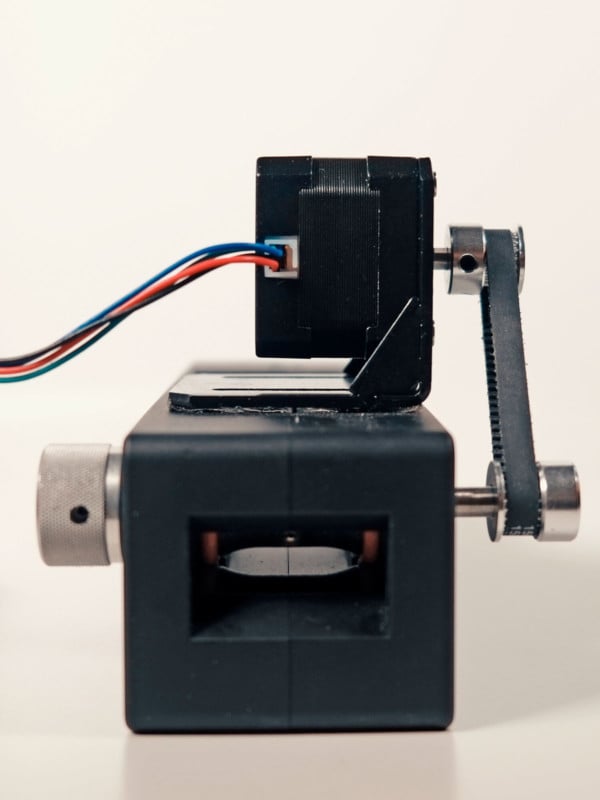
This part of the project is perhaps one of the most fun parts as things start to take shape. It’s the easiest part, but paradoxically the hardest part too. The crucial part to pay attention to is to make sure the tension on the belt is equal during the rotation of the shaft. And that it does not pull the stepper motor, as it is mounted by a sticky silicon mounting tape (Gorilla double-sided tape). Also, word of caution, when mounting GT2 timing pulleys and knobs (Figure 3 a, b, and c), please do not put too much force on the screws as the screw thread could tarnish soft aluminum piece. This is what happened with me with the Negative Supply knob.
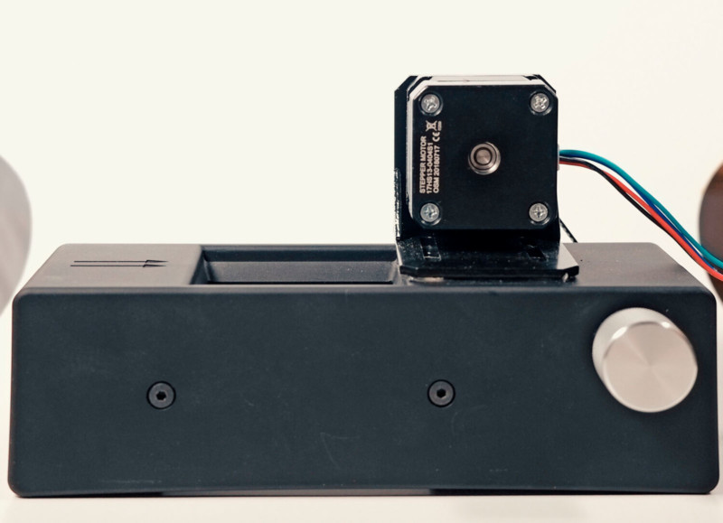
The stepper motor (item 1) is first mounted to the stepper motor holder (item 19). Using the Gorilla double-sided clear tape, the motor holder is mounted onto the negative supply carrier as seen in Figure 3. I used this type knowing it wouldn’t be a huge problem to peel off if needed.
It should look like this at the end when all these pieces are mounted and adjusted. The shaft length could be 1 cm less. But sometimes getting things done is better than just waiting for the perfect piece.
2. The Controller
The controller will be the same for both versions of the film pusher program. However the buttons have a different function except for one, that is the shutter releases. Also, the blue knob adjusting the film progression speed, on the top left, is not used in the full-automatic version. This is because of Python. It is not as good as Arduino IDE when it comes to the precise timing of things.
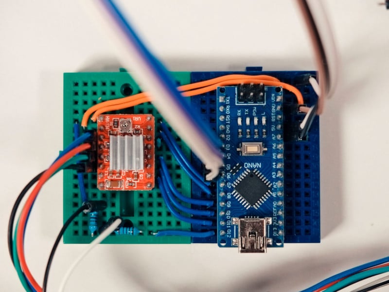
3. Starting with the Arduino Nanon (Blue) and the Stepper Motor Board (Red)
Uploading Arduino sketches are required for both modes. To do this you will need to install the Arduino IDE app. After opening the app, from the tools/board, select “Arduino Nano”, from the tools/Processor, select “ATmega328P (old bootloader)“ and lastly from the tools/port, select that looks like “/dev/cu.usbserial-14xx” for mac users and possibly “ /com3 “ for windows users. Make a note of this address as it is needed for the Python program.
At this point, I would highly encourage you to test out the Blink Sketch that is in the Files/Examples/01.Basics/Blink. A new sketch window will appear. On this window, hit the Upload button that is on the top left, next to the button that has a tick sign. On the bottom left, the opened sketch window will show Compiling Sketch/Uploading/Done Uploading and you should observe an LED on your Arduino Nano blinking. This shows that the board is working and you are able to upload an Arduino Sketch. On my Macbook Pro 2012mid, only the USB port closest to the display port works for uploading Arduino sketches. So, if you experience a problem here, check if other USB sites work on your laptop work.
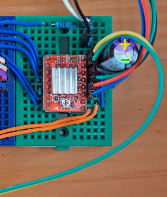
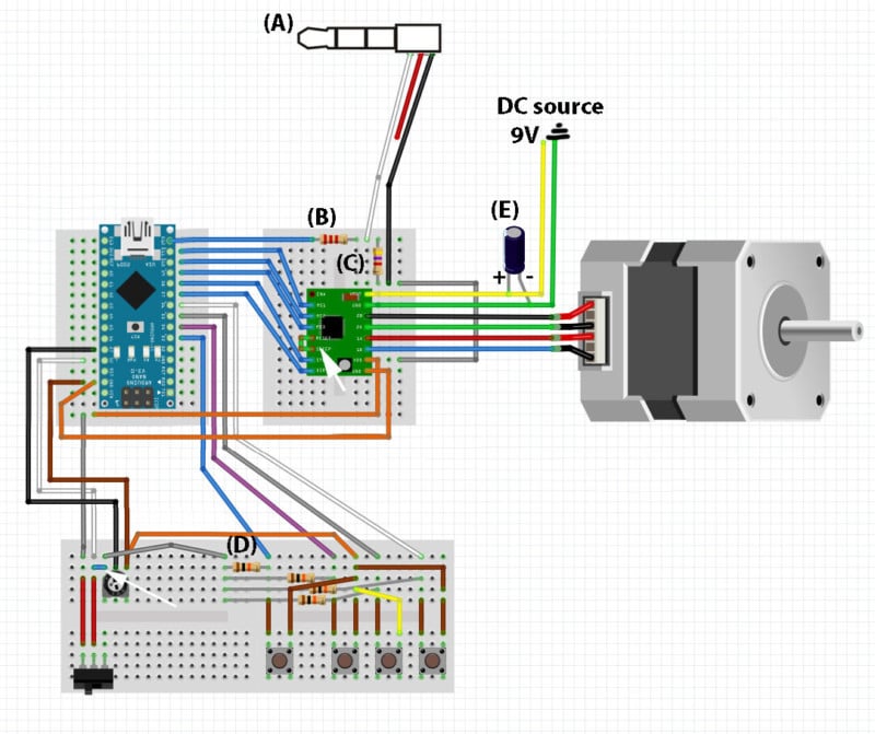
The 2 Orange wires in Figure 6 (side by side on the top part, the other is red but I admit looks orange too) power the stepper motor controller board. Incorrect wiring here will make your stepper motor controller board stop working. Also, pay attention to the wire colors of the stepper motor. The correct wiring will ensure the bipolar stepper motor to receive the voltages in the correct sequence for a successful 360-degree rotation. But this is not as sensitive.
4. The Wiring
This is a simple system to wire and it doesn’t have a lot of components. However, during wiring, it is important to turn off the power.
Let’s start with the 2.5mm jack that is responsible for the camera shutter. You will need a 3 pole jack, Figure 8(A). Using 3 instead of 2 will prevent the activation of the autofocus (manual lens are ideal here). The middle section (red in Figure 8) is triggering the autofocus and is not connected to the mini breadboard. The black wire is ground and the white wire triggers the shutter.
Next, would be to figure out which wire is which on your 2.5 mm jack. One unorthodox yet trusty method is the 9V battery and the tongue sensor. Another way would be using the power of deduction. For this you would insert the 2.5mm jack into your camera, having all wires exposed (white, red, and black). Knowing that the autofocus is activated when the middle section is connected to the right section (probably black), and the camera shutter is activated when the left side is connected to the right (probably white), we can deduce our wires. But I must admit, I am not sure what happens left side it first connected to the middle. Hopefully, nothing :) The best solution would be to use a multimeter.
I usually like to run the stepper motor on 9V as it does heat up over time, but if the tension on the belt is too strong it may need its specified 12V power source.
5. Downloading from GitHub and Getting Started
I have just started using GitHub. It’s an excellent way to track changes and share ideas. If your interested in how Python moves to the correct position, please feel free to check out the algorithm. And also, please don’t hold back to Fork the project and share your ideas. You can find and download them here.
A good place to start is by running the Arduino Sketch. This will ensure correct wiring and components working. To do this download the Semi-automaticUsingArduino.ino from GitHub and upload this sketch into your Arduino Nano as described in Section 3. This should be all.
If your stepper motor is making a funny noise, play around with the blue potentiometer until it sounds correct and the speed is to your liking. If the progression of the film frame is repetitively falling short increase the FrameLength variable in the sketch, and conversely if it is progressing too much. This value is probably specific to your device, as there could be small differences between devices. Make a note of your FrameLength variable, because it will be handy when using the Python program.
If you wish you can change the stepper motor resolution, you can do so by changing the 3 motMS(X)Pin values. For example, with mode 0,0,0 is 200 steps per one full rotation (which is the fastest), with mode 1, 1, 1 it is 3200 steps per full rotation, known as microstepping. This is the biggest spatial resolution we can achieve with this stepper board. This stepper controlling board also has 3 other modes 400, 800, and 1600 steps per 1 full rotation (item 2). This is easier to change in the Arduino sketch that it is in the Python program, as it requires changes at multiple places.
If you want to make the system work in full automatic mode, the Arduino needs a file called Standart Firmata uploaded from the Arduino IDE. This is sketch is found under File/Examples/Firmata/StandartFirmata. This makes the Arduino Nano ready to interact with Python. On the other end, the Python library responsible for communicating with Arduino is called pyFirmata. Hopefully, pyFirmata is already installed either from the Anaconda-Navigation window or by PIP install, along with Cv2, Numpy, and SciPy. The time library is a standard library that is already installed. The Python program is called Full-AutomaticUsingPython.ipynb and can be downloaded from Github.
6. Items Used and Costs
I generally used Amazon to purchase what I needed for this project. This was mostly out of convenience. It also didn’t require me to physically go to shops during the pandemic. I also sometimes when for the faster delivery option. That meant that I usually bought more parts than I needed. I justified this to myself because I thought I would use it on other projects.
If you also end up with parts you do not need at the end you can always donate them to your local schools. I spent about 300 Canadian dollars on this setup. And I now have enough resistors, capacitors, jumper cables, and Arduino Nano’s to last me a lifetime. However, I think you can reduce the cost to about $100-150, if you scout and search the internet for sites like Alibaba, eBay, etc.
A quick disclaimer, if you use the links below for your purchase I will receive a small commission. This little kickback could also motivate me to share other projects in the future. Using these links does not affect the price. That said, I also suggest you use other websites for cheaper prices.
0. Venus Laowa 65mm f/2.8 2X Ultra Macro Apo Lens. I really like this lens.
1. The stepper motor. (On paper this is identical to the one I have used. I just hope the shaft diameter is the same. Unfortunately, the one I bought is no longer available)
2. The stepper motor driver
3. The microcontroller
4. The HDMI to USB out video capture card
5. Belts (158mm was used)
6. 100mm x 6mm Stainless Steel Round Rod (Also currently unavailable). In the future I might try 6.5 or 7mm diameter.
8. Resistor box (4 10k Ohm was used on the controller, one 2k Ohm and one 5k ohm was used as a voltage divider for the camera shutter release)
9. Adjust the stepper motor speed when using only Arduino (not needed for Python aided)
10. Hex key 1.27 and 1.5 were used to make the new shaft
11. DC power supply. I cut out the wire to expose them and used alligator clips to power the board. This is not a long term solution.
12. Essential for connecting the circuits. However you will have way more than you need
13. This wire was handy for the shutter cable, but it might not be necessary
14. This mounting tape was quite good. The adhesive was strong and I was able to take it off without a trouble
15. Way more than what is needed, but I used this kind of button
16. Only one GT2 pulley was used on the stepper motor (Teeth: 20, 5mm diameter)
17. Switching off and on the stepper motor (very important if you want to use the film carrier handle)
18. I used 1000uF 35V capacitor, which was a overkill. A 100uF 25V should suffice
19. Motor mount
20. Electrical tape for solderless wire connections
21. 2.5mm 3 section jack (turns out you don’t need to cut your shutter release cable)
22. Teeth: 20, 6.35mm diameter used on the shaft
I hope you enjoyed this how-to manual.
About the author: Seckin Sinan Isik is a photographer exploring the world of analog. The opinions expressed in this article are solely those of the author. You can find more of Isik’s work on his website, Facebook, and Instagram. This article was also published on his blog.