How I Built a Star Tracker for DSLRs
My name is Gerald Gattringer, and I’m a photographer based in Austria. I recently built myself a custom star tracker for DSLRs, and it works pretty well! In this article, I’ll share how I did it.
The concept I used is called a “barn door tracker”.
I am a university student who really enjoys astrophotography, but I didn’t want to spend a lot of money on a star tracker/equatorial mount, so I spent this winter with building my own.
It can track up to two hours with pretty good accuracy (extendable with longer rod).
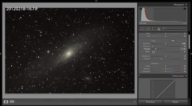
Here’s the first real picture I took with this star tracker:

I exposed the sky 20 times for 90 seconds and the foreground 4 times for 120 seconds. I stacked the sky with DeepSkyStacker and the foreground with Photoshop’s median blend mode. Then I merged the two resulting images in Photoshop.
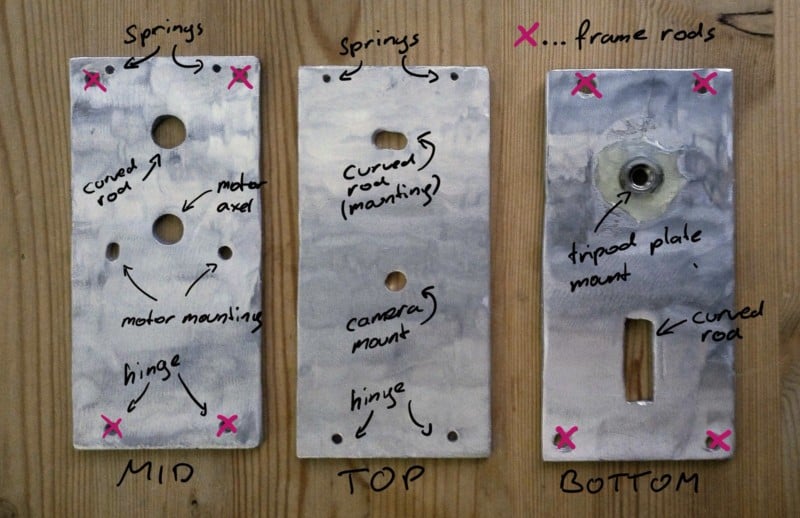
Here’s the build. These are the three plates on which everything is mounted, before painting:
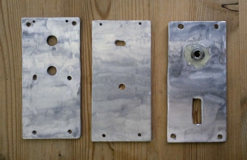
I cut them out of a sheet of aluminum using an angle grinder. I also roughed up the surface so that the paint sticks to them more easily.
I glued the 1/4-inch screw in the hole I drilled using epoxy resin.
I then used standard black metal coating.
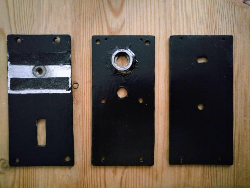
I glued two strips of sandpaper to the lowest plate (where the tripod is mounted), so the tripod’s quick release plate makes firm contact with the tracker.
I glued a washer to the rod hole to minimize the belt drive’s big wheel’s friction.
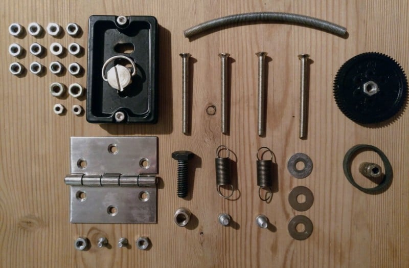
I bought a standard M5 rod and bent it. I measured the distance from the hinges pivot point to the hole where the rod goes through and drew a circle with that radius on a large piece of paper. Then I gradually bent the rod. Small imperfections are ok because I use a belt drive.
I used a gear I had lying around and glued a screw in it for the big wheel of the belt drive.
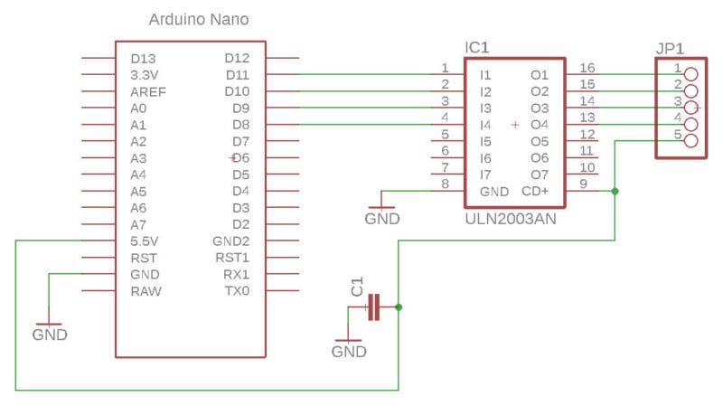
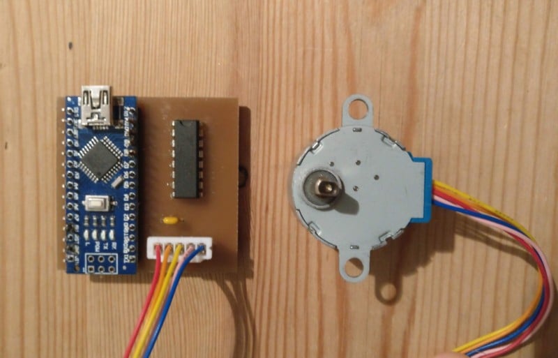
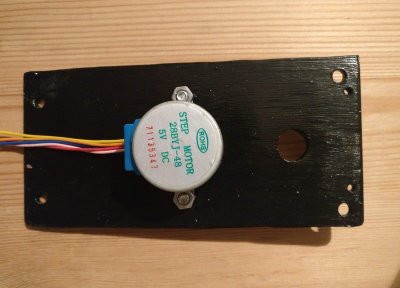
I used an Arduino Nano as microcontroller paired with a ULN2003 to amplify the signal from the digital out pins for the motor. The motor is a 28BYJ-48 stepper motor. The condensator has 100nF.
It turned out that the 5.5V out pin gives me enough current to drive the motor so I connected the 5.5V out to the V+ of the IC.
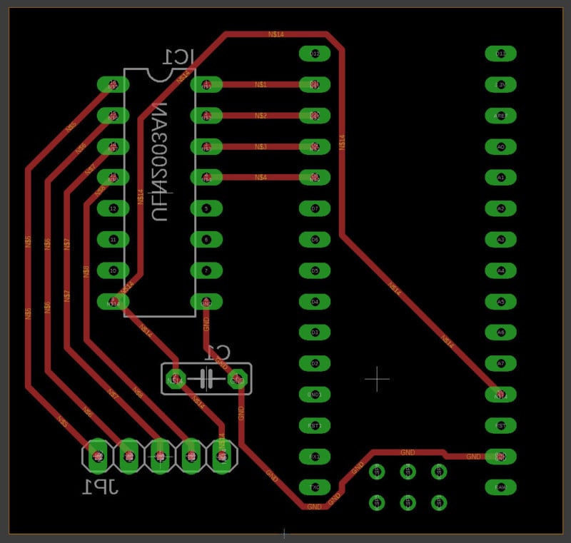
At my university, I have access to a CNC mill (minimill.at) that some students built, which I used to mill the PCB.
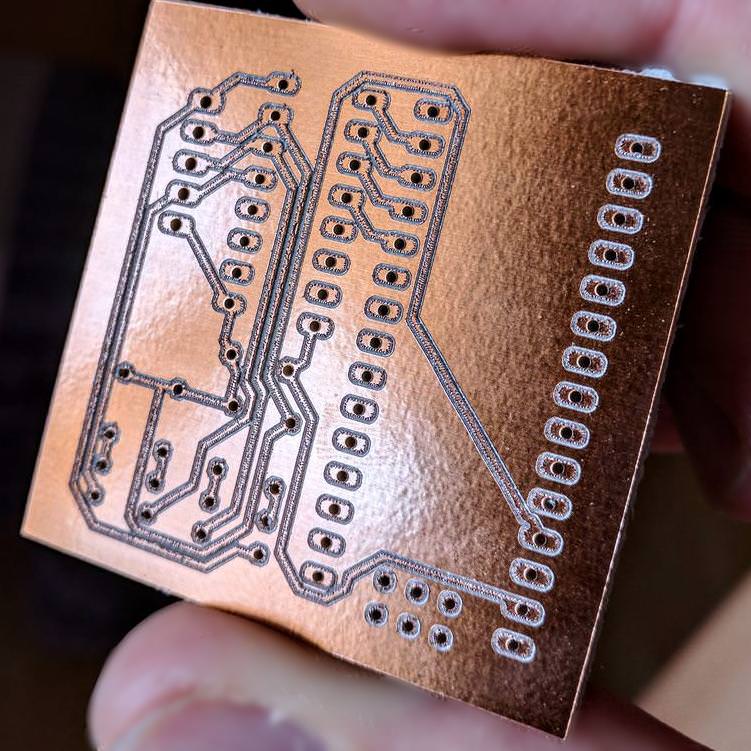
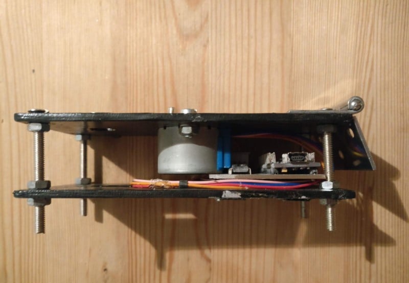
Because the microcontroller can provide enough current for the motor, the mini-B USB port is all I need for powering the device (which is great because I can use a standard power bank with a USB A out).
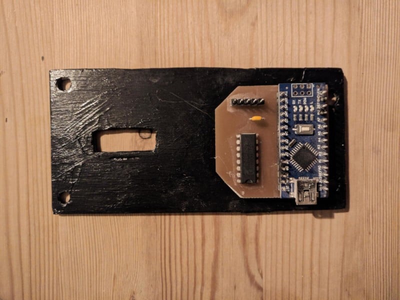
I attached the PCB on the bottom plate using hot glue. The hot glue also acts as an isolating layer between the aluminum plate (and paint) and the circuitry. Insulating tape does the rest.
Here’s the code for the Arduino — it’s nothing fancy, but it does the job:
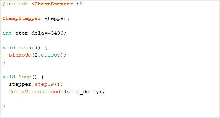
The step_delay value depends on the exact geometry of the device. I tried to calculate it based on the motor speed and transmission ratio but the results were a bit off. I found this value with trail and error.
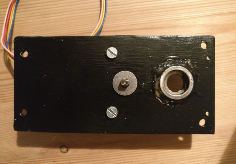
The motor mounted from the top:
…and bottom:
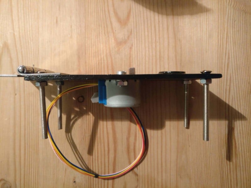
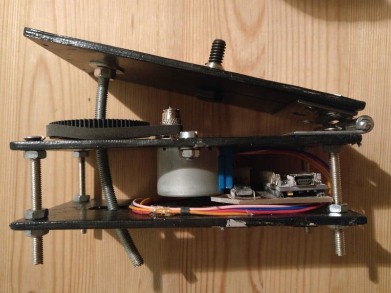
…and side:
Lower assembly is finished. Some hot glue has been used for cable management.
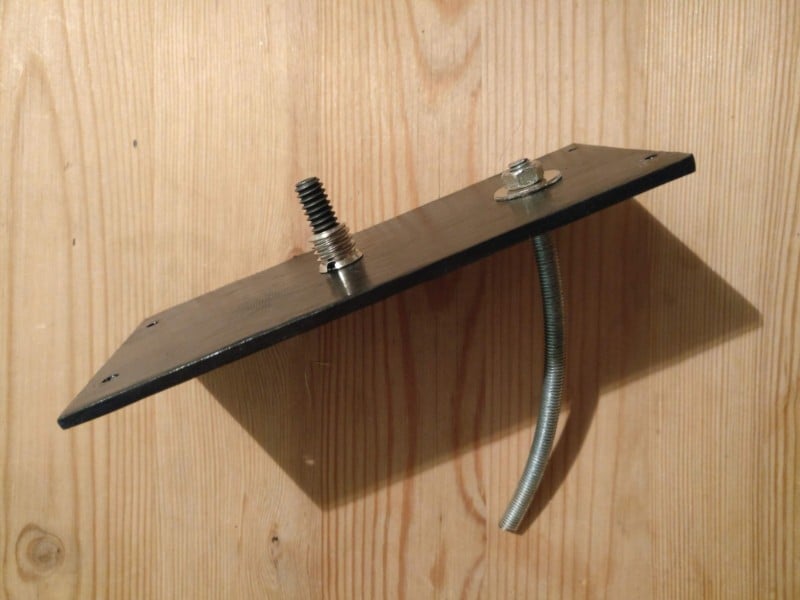
I used a 1/4″ screw to mount the upper ball head. Because the ball head needs a 3/8″ screw, I used an adapter with also holds the screw in place.
I fixed the bent rod with a washer and a nut on either side.
Now, I simply mounted the upper plate on the hinge.
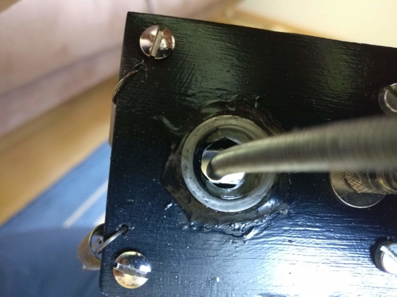
The rod must not touch the plates. Otherwise, the thread will cause small vibrations that you’ll see in resulting images. (Note that I have also attached two springs. I’ll explain further down why I need them.)
At first I used the plate as a guide for the rod, but it did not work.
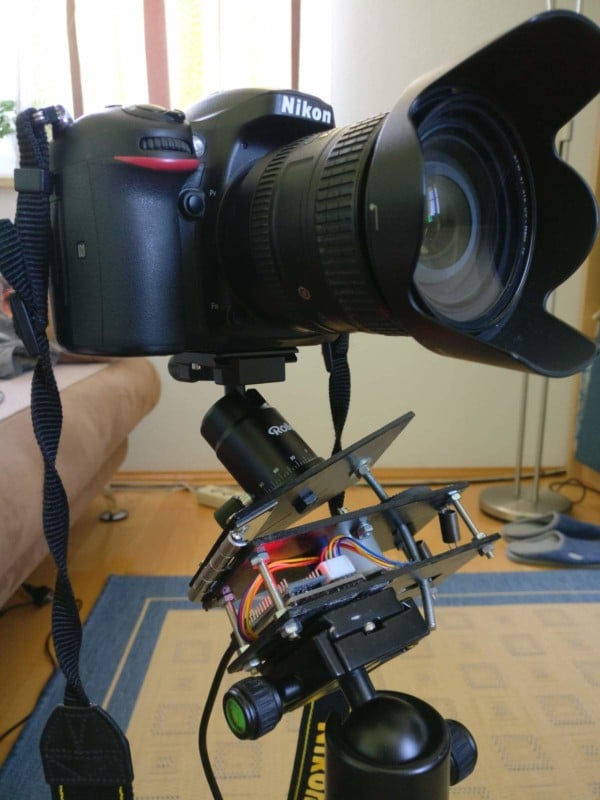
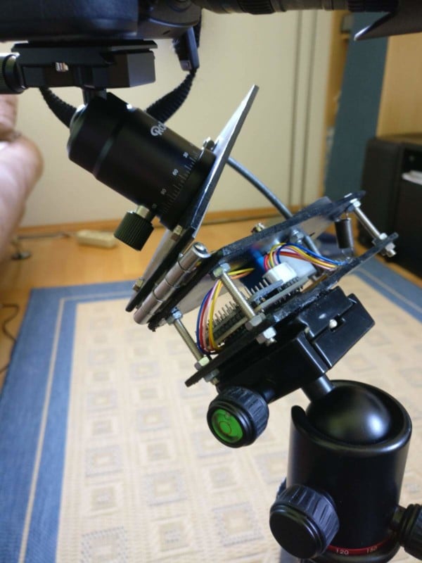
The star tracker is finished:
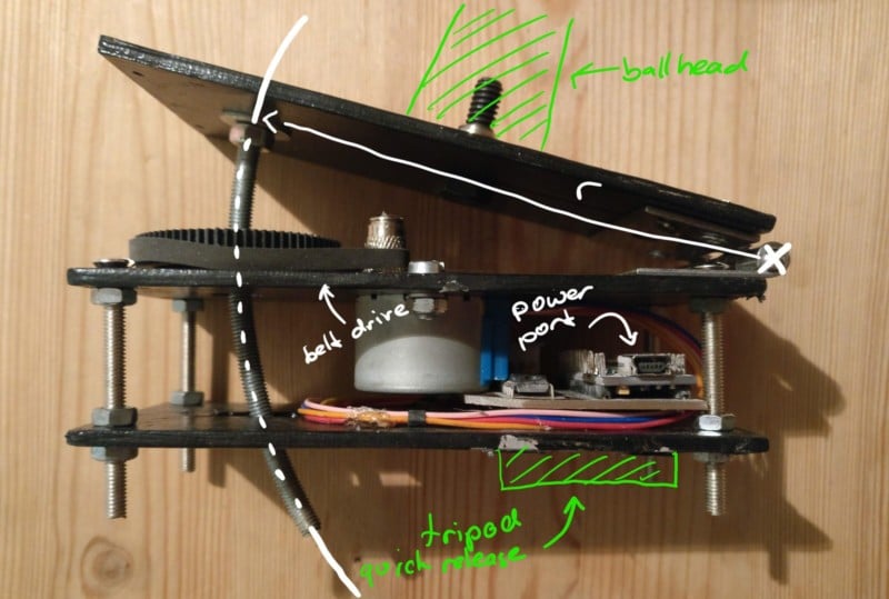
Here’s the belt drive in action (it turns the big wheel at the exact speed that is needed to lower the bent rod at 15°/h):
The motor turns the big wheel of the belt drive which has a nut in it. Because the big wheel can’t move down, the rod does and therefore turns the camera. The radius ‘r’ in the picture is the radius I tried to bend the rod.
For the tracker to work correctly you have to align it with the Earth’s rotational axis.
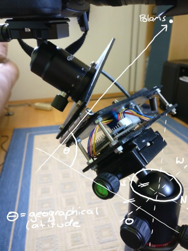
Here are two ways to achieve this:
Option A: Point the axis of the hinge to the north star.
Option B: Point the axis of the hinge north. Set the pivot up so that it sits flat with the ground (theta=0°) then pivot it up. The angle (theta) between the ground and the tracker is equal to your geographical latitude.
I prefer the second way because you can set up the angle in advance and simply have to point the whole thing north when you start shooting.
Now you can also see why I have optional springs on the construction: when the camera points south at a “bad” angle gravity may pull the hinge open. To circumvent this the springs can be spanned from the mid plate to the top plate to hold it down.
An early but functional test build:
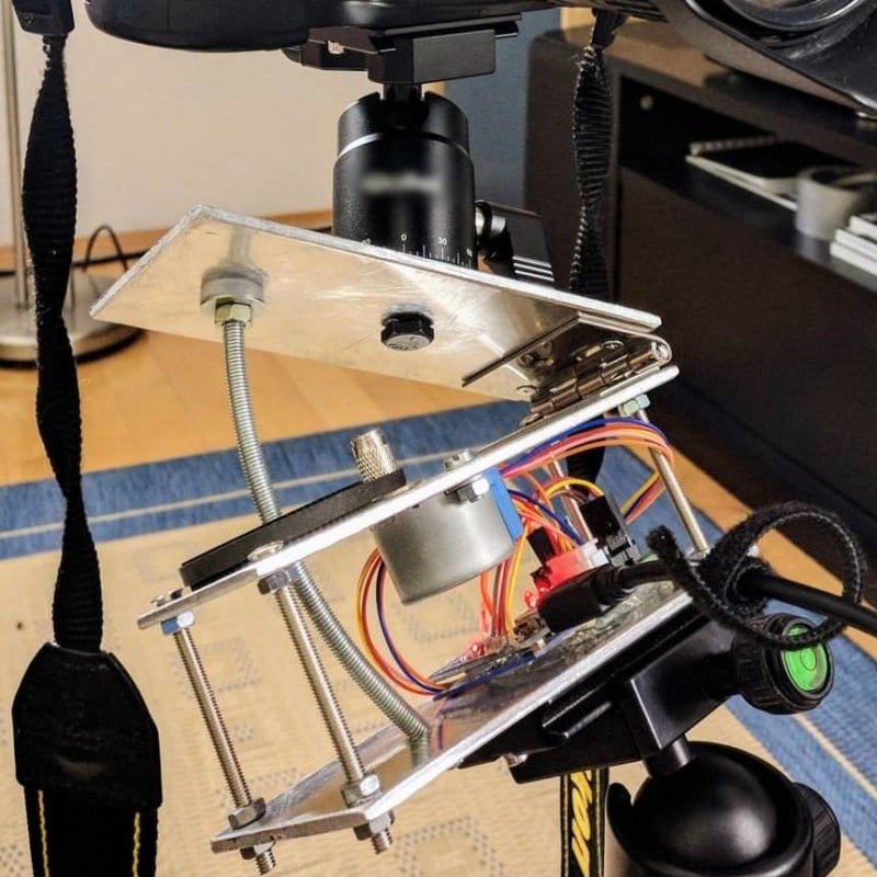
I measured the angle let it run for an hour and measured it again to find the optimal motor speed.
I have seen some trackers that open the hinge, but why work against the gravity? My setup closed the hinge at 15°/h (360°/24h -> 15°/h).
I used the small PCB that came with the motor to drive the motor.
I also removed the rubber washers where the rod mounted because it made the whole construction more fragile and was useless anyway.
This version is bigger and slightly more fragile but lacks the need for a custom PCB.
And here’s the finished setup:
About the author: Gerald Gattringer is a university student and astrophotographer based in Austria. You can follow along with his work on his 500px.