Bending Pixels: Fun Things You Can Do With Panorama Stitching Software
One of the great workflow possibilities that was opened up by the advent of digital photography is the ability to easily create panoramic images. It’s become trivially easy to generate panorama images, so much so that it’s even become an integrated feature into smartphones.
What many photographers may not realize is that there are a number of other interesting results that can be created using panorama creation software, if you just keep in mind what the software is actually doing (and what you are actually telling it to do).
Software
I primarily use Free/Open Source Software (F/OSS) wherever I can, so my panorama software of choice is Hugin (based on panotools). There are many other programs that will do panorama stitching, but most tend to hide the complexity of manipulations to the end-user. Autopano might be suitable, but the general processes I’ll describe below should be reproducible in other software.
Panoramas
Without getting “outside the box” there are already interesting things that can be done with panoramas. It helps to understand that what the software is basically doing under the hood is mapping all of your images to the inside of a sphere, the center of which is located at the nodal point of your camera. (If you’re really into getting perfect panoramas, it helps to have a tripod with a panorama head – but you can get really nice results going handheld if needed).
This all occurs during the actual stitching of the images together, usually based on lens/sensor parameters as well.
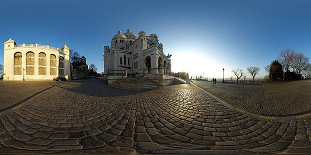
Once the mapping has been done, the software has to determine as way to represent that sphere of image data to you on a 2D screen. This is where projections come in. Suffice it to say that the majority of panoramas that you may have viewed are likely presented using common projections such as equirectangular and rectilinear (depending on material).
Here is an example of an equirectangular projection of a full 360° panorama.
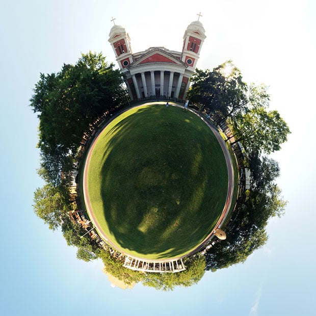
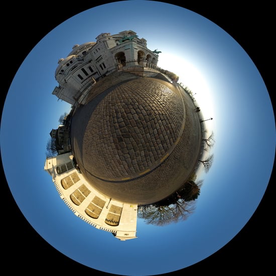
A great example of trying something different with the software is to modify the projection of this data from equirectangular to stereographic (and a rotation). This yields a very interesting result often referred to as “Wee/Little Planets”:
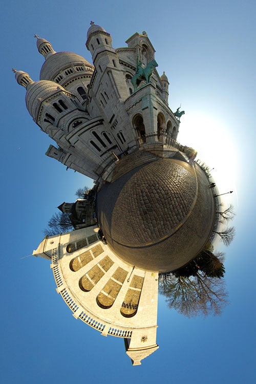
Indeed, many people may suggest attempting to create this effect using something as simple as a polar coordinate transform in Photoshop/GIMP, but as I’ve previously written, the results are often less than satisfactory:
Architectural Projections
View cameras have some interesting characteristics that are often sought after in modern digital cameras with fixed planes between lens and sensor. A good example of this is the emulation of “tilt/shift” images:
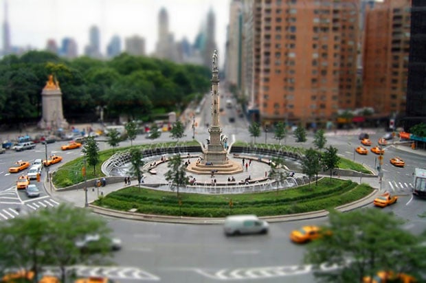
This effect is produced in view cameras by modifying the front plane with the lens relative to the film plane on the back plate. One of the really great capabilities of having the lens plane adjustable relative to the film plane is that the image can be shifted while maintaining orthogonality with the subject.
This comes in particularly handy for shooting architectural subjects where you want to maintain parallel lines in the image. Shooting a building from ground level for instance will often require the photographer to pan the view up in order to include the top of the building. Doing so will lead to converging parallel lines.
View cameras have the option of shifting the lens up vertically to include the top of a building without having to tilt the film plane. This allows all of the parallel lines to remain parallel in an image:
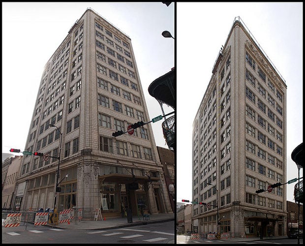
The image above is stitched from 3 images. On the left is the rectilinear projection after correcting for lens distortions. From the same panorama, the right image was generated, but in this case the vertical lines of the image were identified in the software. This produces an “architectural view” (really axonometric, or really really planometric).
The view on the right is possible without modification using a view camera, but can be approximated using a few extra control lines in the panorama software.
Lens Distortion Correction
Speaking of control lines, the software can also be used to generate lens correction parameters as well. In the previous example the image was corrected to maintain parallel lines in rendering the final output. The same technique can also be used in reverse to correct for lens distortion.
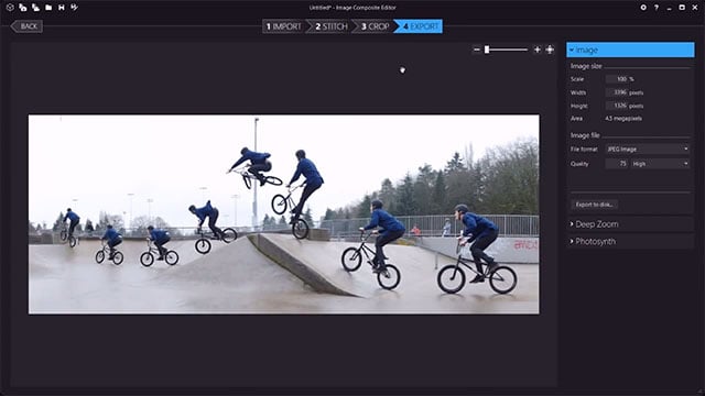
If you start with an image (or images) that have known straight lines in them, they can be used to generate parameters to automatically correct images later. There is a tutorial on the Hugin site that walks through the process. The basic idea is to shoot photos of an image that has known straight lines in it, identify points along these lines as straight lines in the software, and to run an optimization against them:
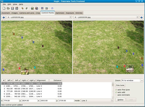
Once the optimization has finished it will produce lens parameter values that can be saved for re-use in the future (or modified for use in other software) to automatically correct lens distortions.
I’ve found this same method to be useful when generating RAW+JPG during a shoot, as the RAW file will be uncorrected. If I want parameters that will match the same result as the in-camera JPG, both can be opened in Hugin, and correction parameters can be generated to match the RAW to the JPG distortions.
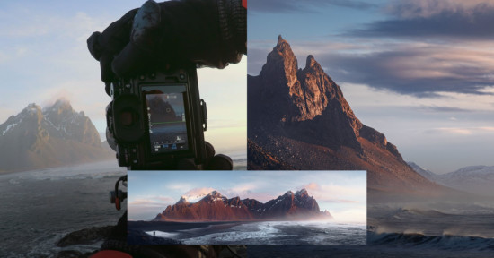
Overlay/Align images
The stitching and alignment of images also works for multiple images of the same scene. In this case it is just a pure image alignment. In fact, the open source HDRi software LuminanceHDR uses Hugin behind the scenes for doing the initial alignment before creating the HDRi (align_image_stack).
Besides being able to align the image stack for HDRi creation, it also allows for an interesting solution for fixing transverse chromatic aberrations. Each of the RGB channels of an image can be brought into the software and aligned to help reduce errors caused by TCA in the image.
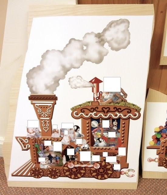
One interesting use of this was to correct a problem that someone had where they had taken photos of artwork on display, but didn’t set the white balance properly. So the resulting photographs had some very nasty color shifts. Fortunately they still had the high quality artwork used to produce the work being photographed. Rather than attempting to fix the white balance only, the original artwork was mapped into the photograph to represent the correct colors:
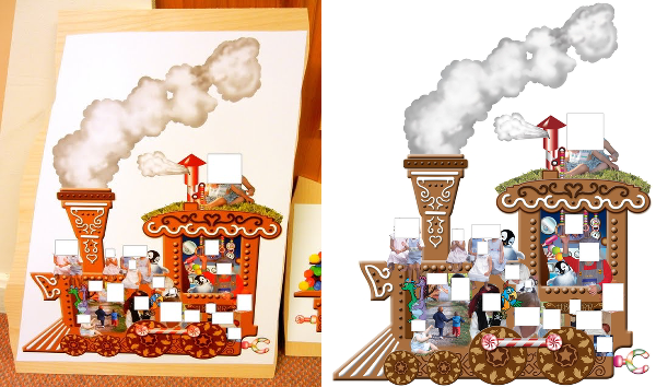
The original image on the left had an improper white balance, and was only in JPG. Correcting for the white levels produced a nasty color shift in skin tones and artwork. So the image was corrected as much as possible for the background and whites, and the original artwork on the right was mapped into the photograph:
In Conclusion
These are just some of the interesting methods that are available for image manipulation. If anyone has found other uses for pixel bending software, I’d love to hear it!
Image creditsSacré coeur by gadl, Sacré coeur by gadl, Columbus Circle NYC fake tilt-shift by avhell