How to Do Water Ripple Tank Shadow Photography
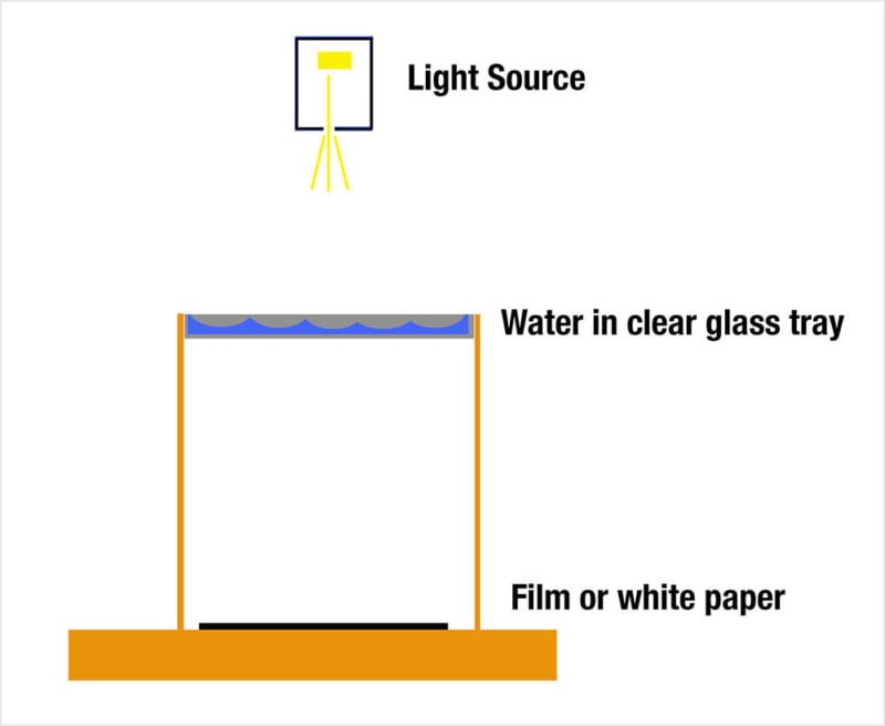
A simple ripple tank is the mainstay of every physics teacher’s demo collection. The typical demonstration is done with a point light source of a little tungsten light bulb a few feet above the ripple tank. The ripple tank is in reality a shallow pan of water with a clear bottom. The ripples are observed by placing a sheet of paper a foot or so below the pan of water.
Surprisingly, the demonstration was expertly photographed by the famous Berenice Abbott for a number of science textbooks in the 1950s and very few photographers have explored the topic since. The textbook is Physics by Physical Science Study Committee (PSSC). Although Berenice Abbott created the majority of the photographs in the book, she is only credited as a contributor to the program one name among several hundred.
In the book about Abbott’s photography, Imaging Science, she writes about all the problems she had removing dust from the water. Any speck of dust will be enlarged on the photographic paper exposed below the water tray. In my experiments, I placed large sheets of film at the bottom of the water tray and exposed it there. I still had problems with dust landing on the water and being imaged on the film. Once the film is processed and scanned the dust can be removed, but it still takes time and is annoying.
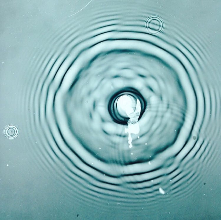
Here is one of my experiments showing a negative that was exposed in the bottom of a ripple tank. The drip of water was programmed with an Arduino microprocessor that also triggered the speedlight flash at just the right time. The speedlight was covered with tape to limit the light opening to a circle about 3/8th of an inch in diameter and placed 6 feet from the film. The closer the light source is to a point source the better. The Speed light was also set to the fastest setting. This image above is a negative.
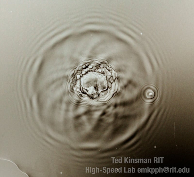
To see how close, I could get to the film look, this image is taken of the ground glass with a 105mm Sigma lens. The light source here was also a speedlight flash on the fastest setting. This image was also converted to a negative to compare with the above image.
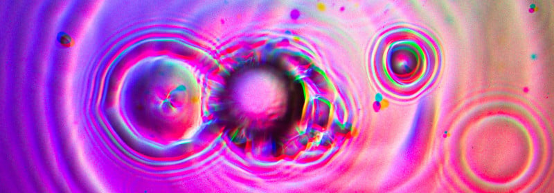
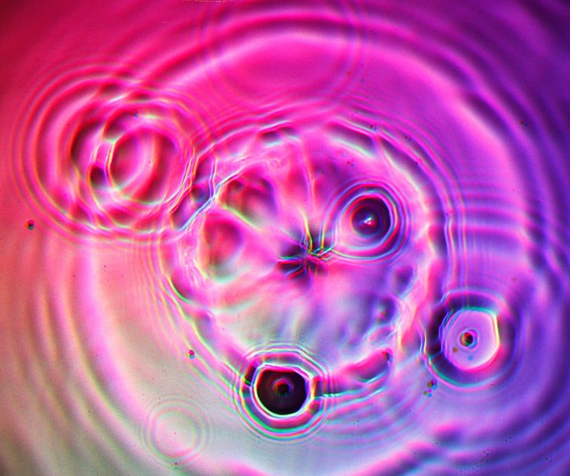
To update the experiment, and add some color to the ripples, I have replaced the tungsten light sources with three 10 Watt 12 VDC LED light sources. I use a red, green and blue LED each placed around the dripper that is above the water tank. The green and blue LEDs were placed on a variable resister and adjusted so that the combined light was just about white. The digital camera has different sensitivities to different wavelengths so the LEDs have to be adjusted in intensity. If you are going to convert your images to black and white, you do not have to adjust the LEDs.
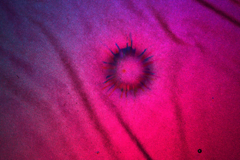
To see if I could use a ripple tank without a ground glass bottom, I tried to use some fine rice paper at the bottom of the tank. Here the paper has been absorbing water and showed its wrinkles. On the left is an early splash, while on the right is a splash later in time.
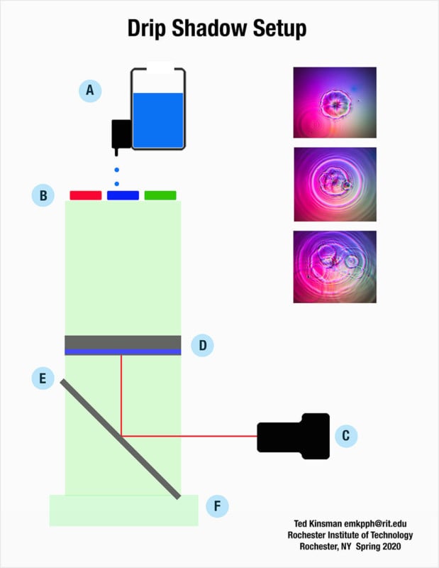
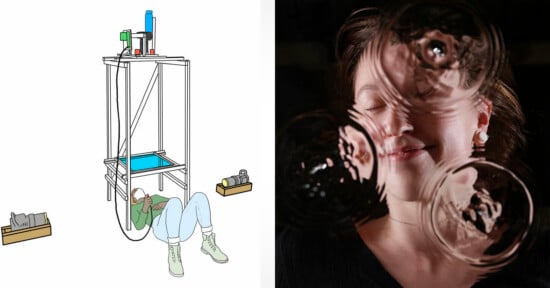
A: The Arduino controlled dripper.
B: The location of the 10Watt LEDs in a pattern around the drip nozzle.
C: the camera is aligned to the center of the ripple tank.
D: Is the ripple tank the bottom surface has been ground with 400 grit aluminum oxide to scatter the light. The ground glass is facing the camera.
E: is a front surface mirror. The mirror keeps the camera away from the water.
F: Is the wooden stand that supports everything.
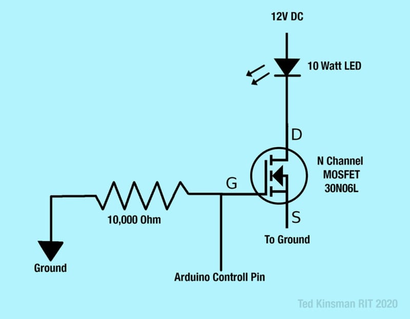
The control circuit for the 10Watt LEDs is just an N Channel power MOSFET controlled by the Arduino on the gate. Each LED takes about 1 amp of current. The Arduino control pin works best with a 10,000-ohm pull-down resistor on the gate. The power MOSFET does not need a heat sink if it is only turned on for a few seconds. If you are not using the LEDs as a high-speed flash you might want to directly wire the LEDs to the supply. Not shown in the schematic is a variable resistor to balance out the color intensities for the digital camera.
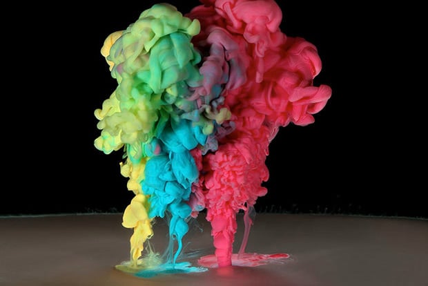
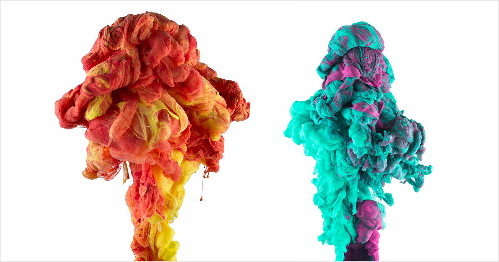
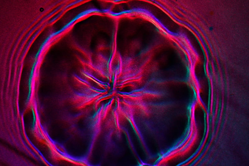
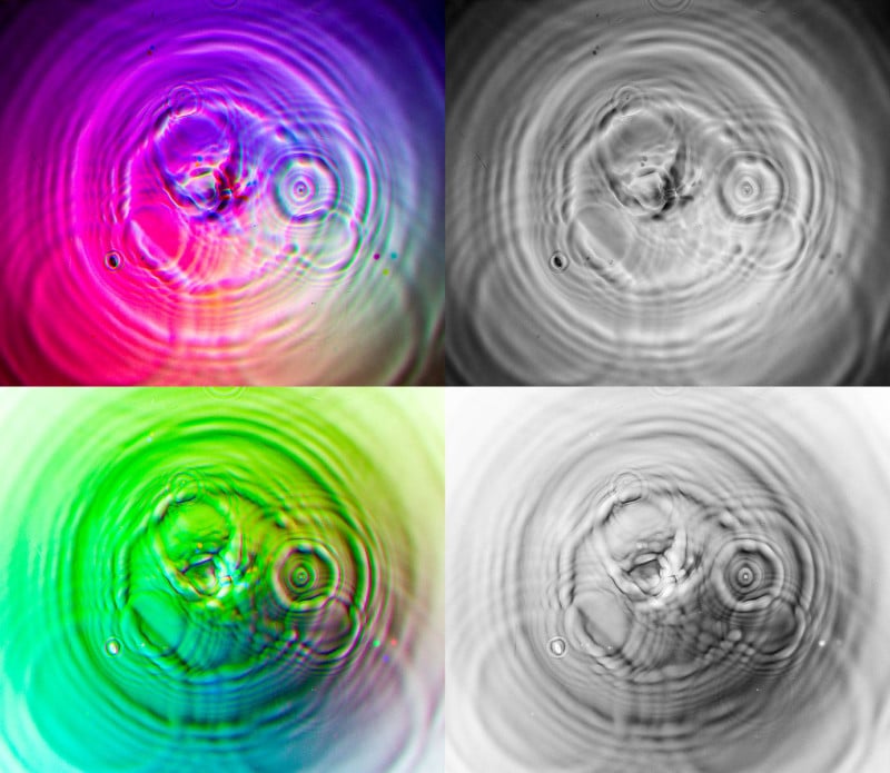
A small selection of images collected from the LED ripple tank:
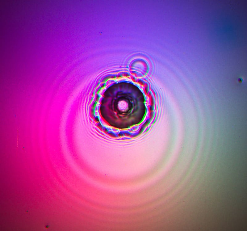
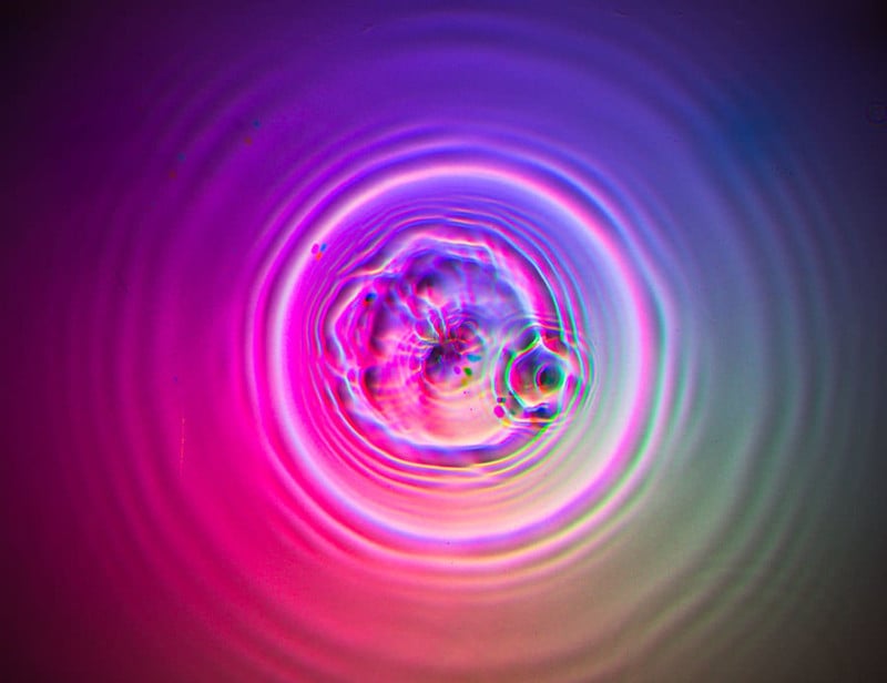
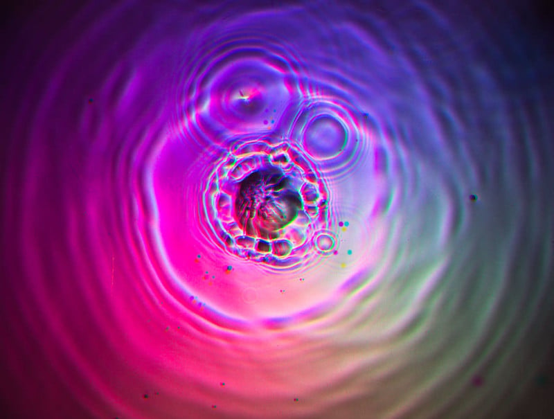
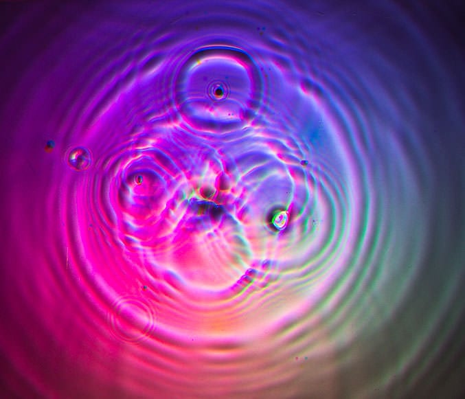
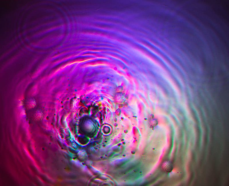
Since the colors can be desaturated, and the image flipped to negative, it is often difficult to decide the best way to present the ripple patterns.
The Arduino code for this project can be found here.
For details on a double drip system please read this article I wrote in 2016.
This project is shown in high-speed video at: