How to Build a DIY Double Water Drip System for High Speed Photos
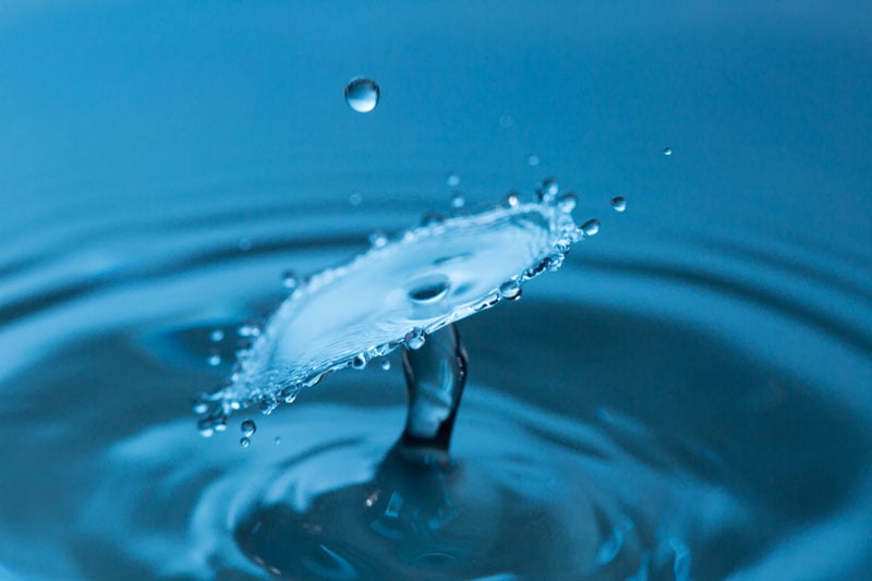
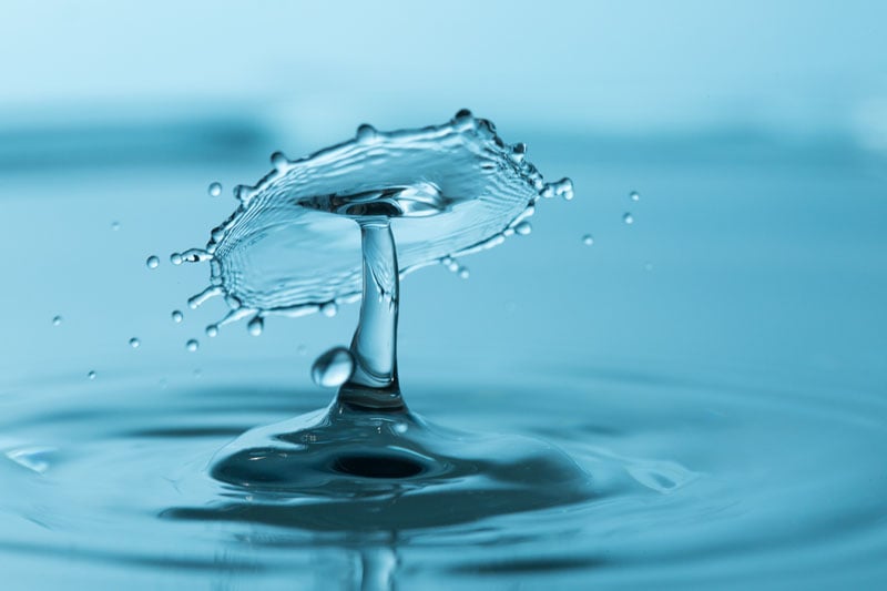
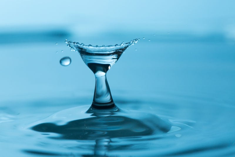
In 2002, a renegade science photographer, Martin Waugh, was playing with high-speed photography and discovered he could image two drips of water hitting each other.
Several companies like Mumford Time systems and Cognisys Inc. make special systems just for this double drip photography. In this article I will explain how you can make your own.
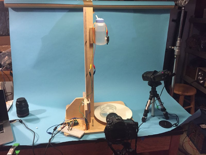
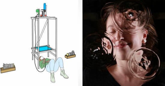
For this project I made a stand for the dripper that was more complicated than needed since I plan on using it for a number of demonstrations with students and need it easily adjusted. I like using 11 layer plywood; sold for cabinets and fine woodworking. This material is 5/8 inches thick. This wood is quite stable, free of voids, and is a lot easier to work with than machining metal. Over the years, this plywood has become my favorite material for building these types of projects.
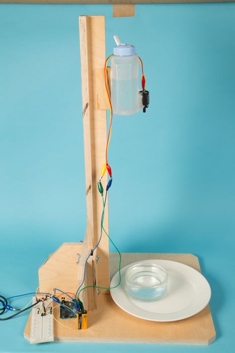
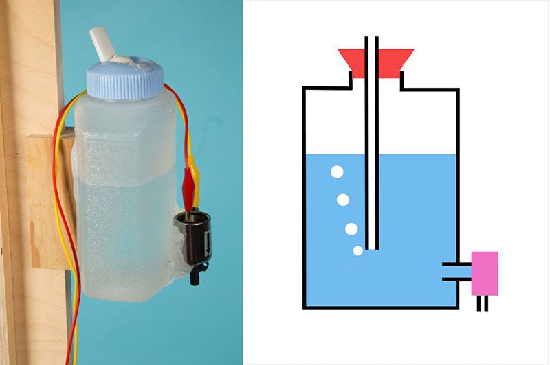
The project is started by making a Mariott’s bottle or often called a Mariott’s Siphon and is a way to keep very constant water pressure on the water valve used in this project. Without the Marriott’s bottle the pressure and thus the droplet size would change with the height of water in the bottle so the system would quickly loose calibration. I use a Rubbermaid Litterless Juice Box model #3115 16oz./500ml, which is easily available at any grocery store. Any bottle will work and I often buy bottles at a discount store when I have a class of students building systems.
To increase adhesion between the plastic bottle and the valve/bracket I recommend using sandpaper to roughen the surface. I like to use silicone adhesive designed for glass for this application. If the design is changed, the silicone can always be cut off. The different plastics often are difficult for the adhesive to stick so, try a few inexpensive bottles to see which ones the glue sticks to the best.
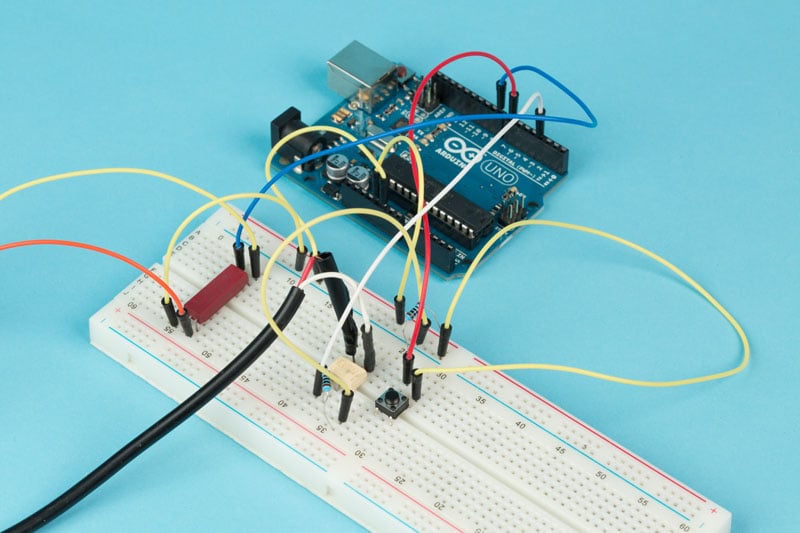
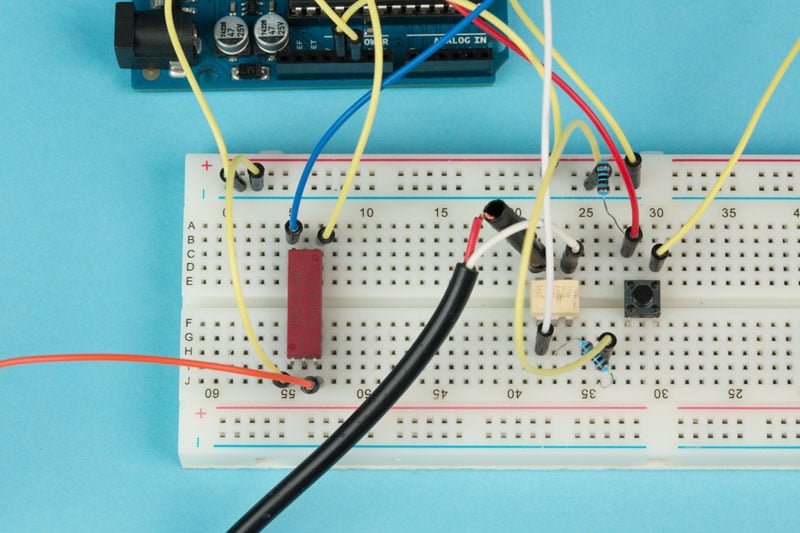
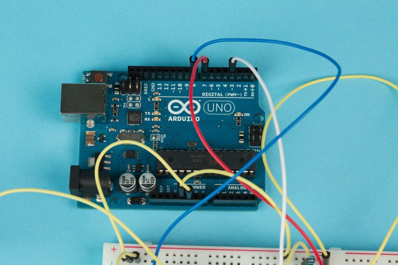
The drip solenoid valve is a 12VDC valve bought from a surplus center. These are easily available for a few dollars online. There are a number of better valves on the market and in general the more you spend on the solenoid valve the better they are in quality. The 12 VDC valve I use is normally closed and works fine on 9 volts. This is an advantage since students can easily run the valve off a 9V transistor battery. This makes the circuits a lot easier and inexpensive since it does not require an expensive power supply.
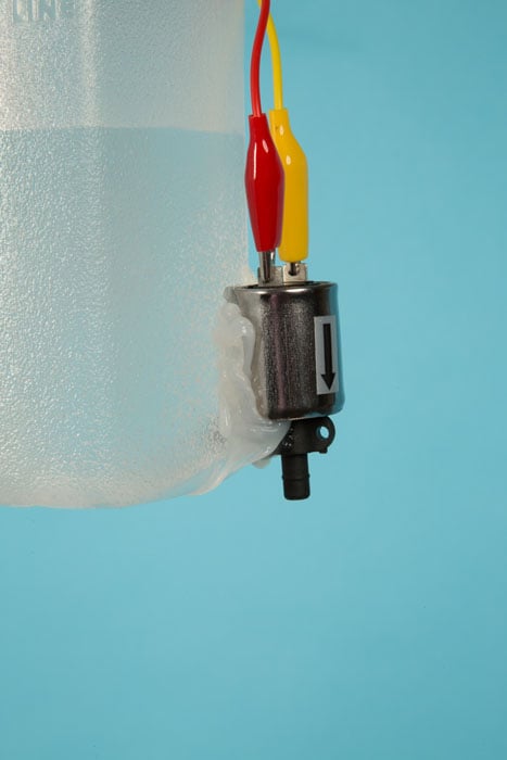
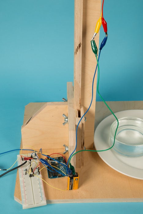
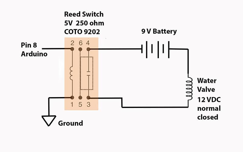
The solenoid valve is controlled by a 5VDC reed switch, which in turn is controlled by a pin 8 of the Arduino. The reed switch is an inexpensive way to isolate the Arduino from the 9VDC pulse that is sent to the valve. The valve takes a lot of current and the reed switch is an easy way to control the valve. The reed switch also makes an audible chirp that is very useful for debugging the circuit. I use the COTO 9020 5V reed switch with an internal resistance of 150ohms available from Allelectronics.com (a nice source for surplus electronics).
The Mariott’s bottle is placed so that the valve to water distance is 44 cm. This distance is where I calibrated the code and valve in my sample program which is a good distance to start. The dripper can be calibrated for any height, but the second drop needs time to hit the first drop, so there is a minimum height that is dependent on the speed of the drip valve. Most of my students find the minimum drip height to be around 20cm.
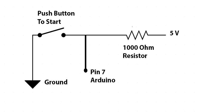
To control the circuit and trigger the Arduino to start, I use a simple push button on the breadboard. The switch is held in a high state by a 1000 ohm resister and connected to pin 7 on the Arduino. The push button connects pin 7 to low and starts the timing of the solenoid valve.
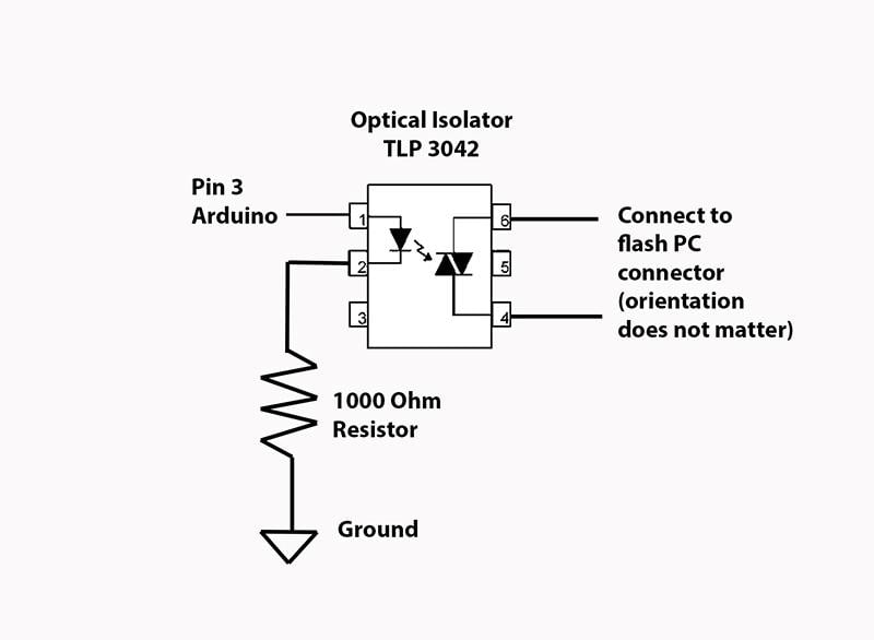
The flash is controlled by an opto-isolator, which uses a triac circuit so the polarity of the flash cable is not important. The opto-isolator is very fast and its’ perfect for the flash trigger that does not carry much current. It should be noted that the opto-isolator can not carry the current required for the solenoid, and would easily blow out if an experimenter tried. The flash cable is a standard male PC connector and is supplied by HiViz.com a site that makes educational kits. Inexpensive cords can also be found on the internet and cut apart. Just make sure you do not cut the connector that matches your flash off.
The flash system is any flash that can be manually controlled to a 1/32 power or lower setting. These low power settings are created by producing a fast flash with a low light output.
You can find the Adruino source code here.
Once the system is set up it is time to adjust the valve and timings. Use // to comment out any of the lines in the Arduino code that you do not want to run. Comment out the lines responsible for the second drip. The first thing to do is change the timing of the ValveOpen variable so that the valve makes one clean drip every time. This time will depend on your valve and is different for every manufacturer. The next adjustment is to change the ValvePause variable to create the two drips to collide with each other – timing it to be exact when the first drip is highest in its recoil. After working with systems for a while you can see the unique splash, so you can correct the timing. Experimenters new to the system can use an Iphone 6 on the high speed setting to see if the splash takes place at the correct time. The use of any video camera will greatly simplify the setup time for the experiment.
The last step in the setup is to adjust the flashDelay variable to trigger the flash at the exact time of the collision. This can be done with a video camera to see if the flash takes place before or after the desired time of the drip collision.
The setup can often be difficult. Be patient and take your time, with careful adjustments you will work the variables and get the shot.
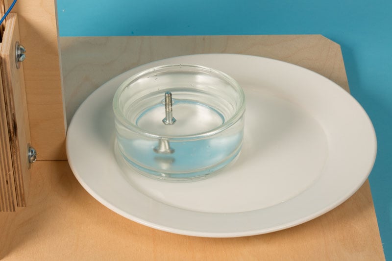
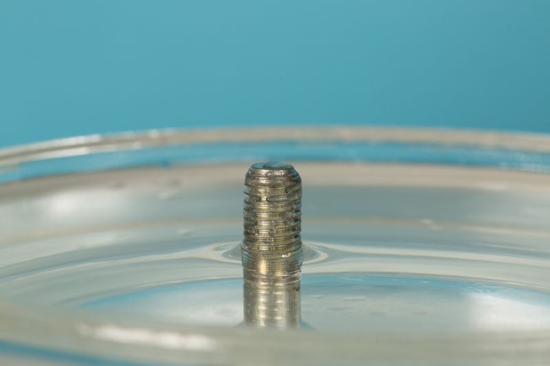
Once every variable is adjusted and the system is triggering at the correct time on every flash it is time to do the serious still photography. In a dark room, I set the camera to bulb and use a 105 mm macro lens. I put a bolt in the drip to give me something to focus on to get the correct placement of the frame.
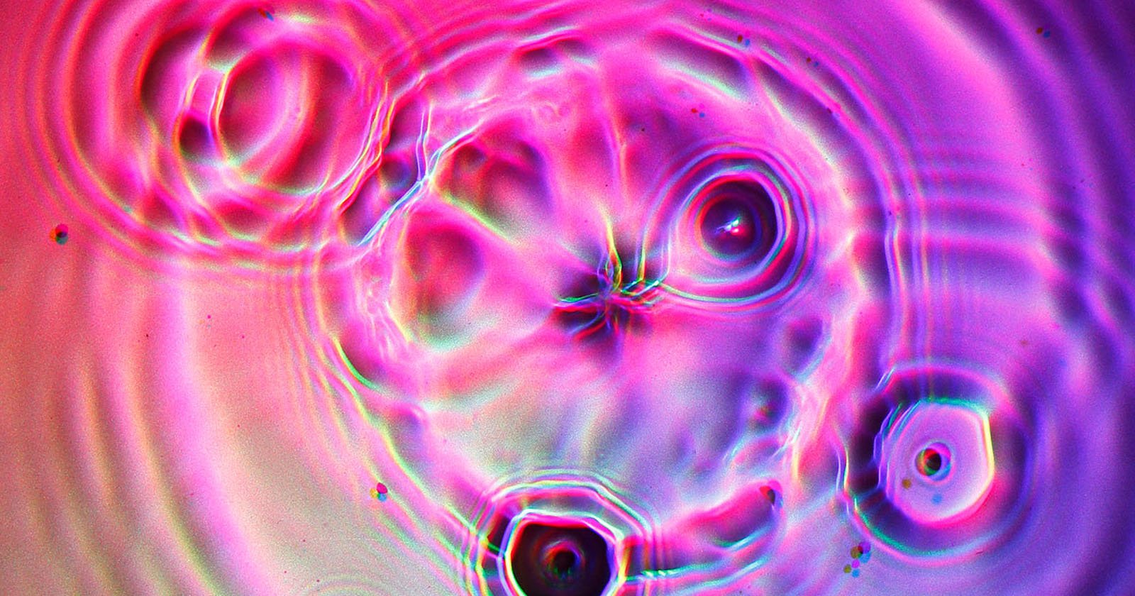
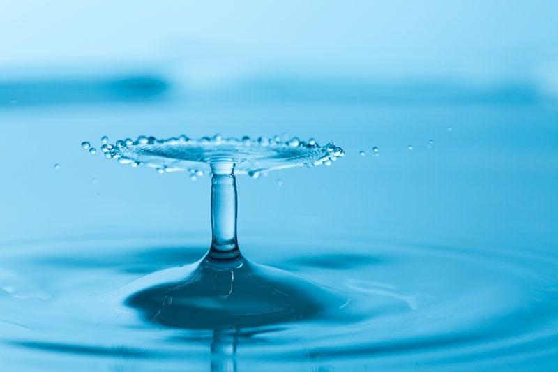
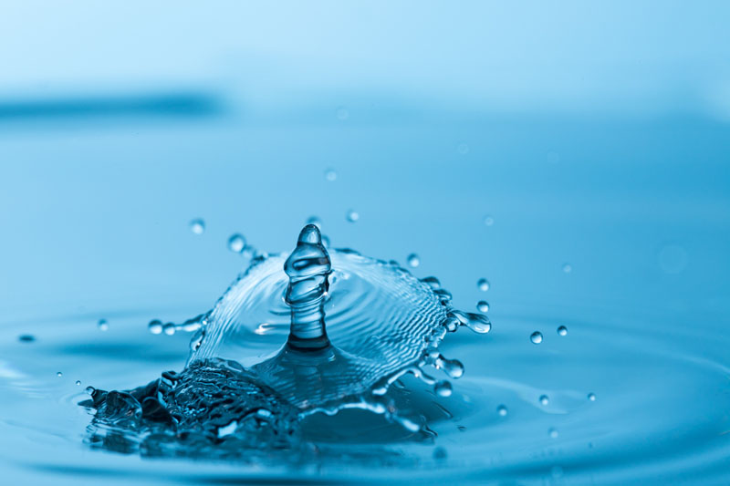
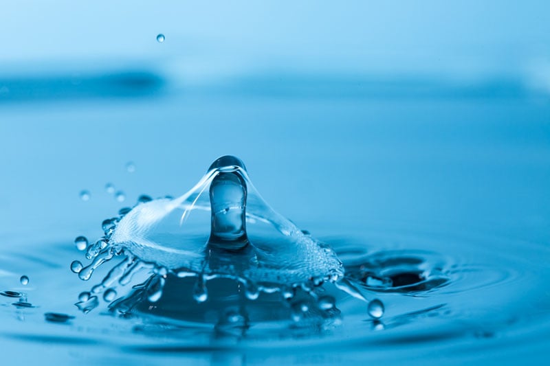
The camera is set to bulb and triggered in a dark room. The camera shutter is opened and then the water drip system is triggered, then the camera shutter is closed. The water is transparent so the background is what produces the colors for the image. The flash is also directed to the background rather than the subject to the drip. The flash I use is a Canon Speedlight set to 1/64th power, which creates a relatively fast flash of light that is able to stop the motion of the water drips. The placement of colored background patterns creates stunning colors in the water droplets.
After capturing a number of great images, the experimenter will be ready to try changing a few variables to get different effects – these include:
- Adding food coloring to the dripper
- Changing background patterns
- Changing the temperature of the water
- Changing the depth of the water
- Changing the viscosity of the dripped fluid by adding guar gum
- Dripping milk
- Dripping two drops at the same time
- Valve height
- Adding a control to trigger a camera
- Adding a second drip valve
Experimentation is just about endless with this simple system.
Once the photography is over for the day it is important to clean out the solenoid valve. The inexpensive valves I use for my class easily rust if water is left in them and will jam up if milk is allowed to dry in the valve. Sometimes a jammed valve can be freed up by using a blunt end of electrical wire pushed through the dripper, lightly freeing up the stuck valve.
This project is a great way for students in just about any level to be introduced to using the Arduino for photographic projects.

This is a great project for a classroom on just about any level from 9th grade. This is also a wonderful project to stress S.T.E.A.M (science, technology, engineering, art, and math) all in one project.