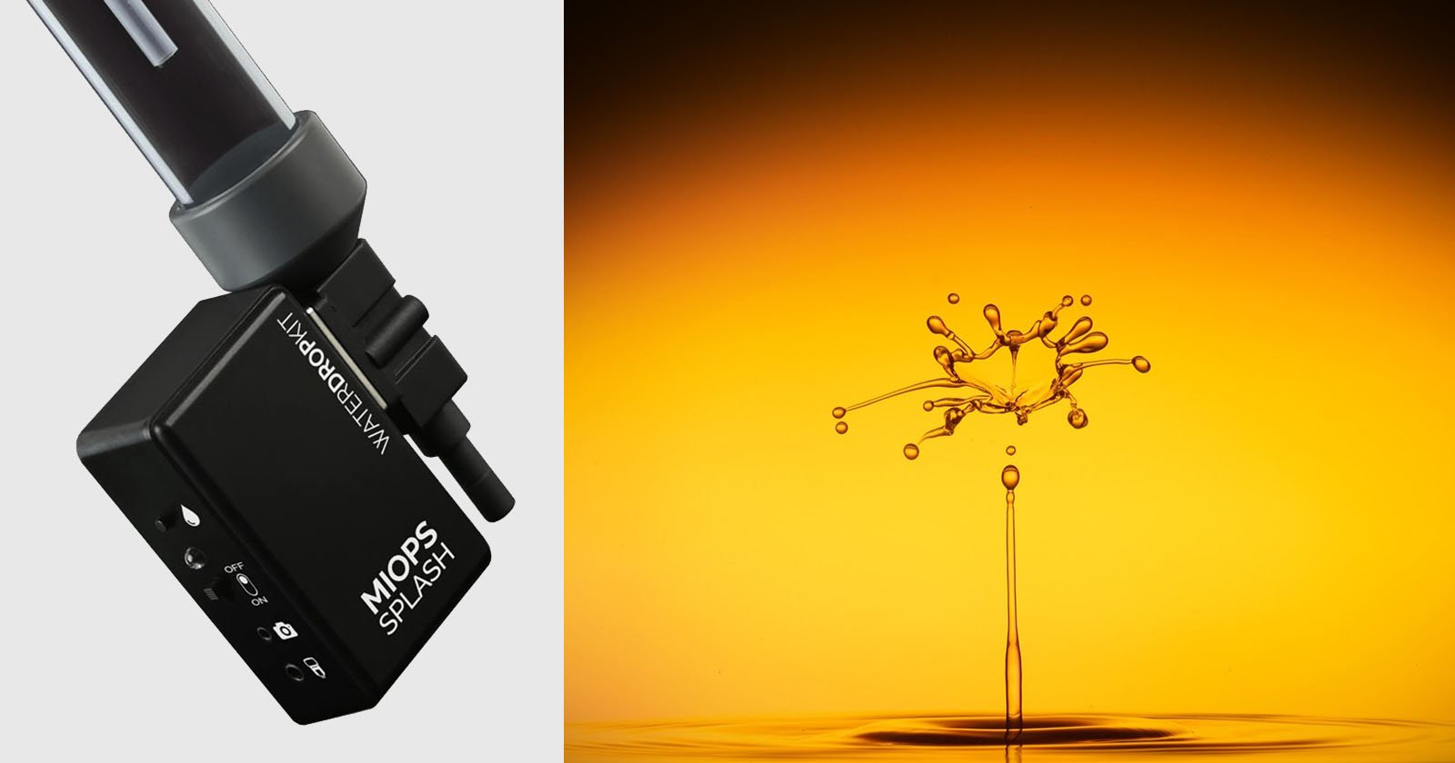
How to Photograph Flowers Splashing in Milk with an Infrared Laser

We came up for the idea to do this shoot when we saw someone on Instagram who was dropping flowers into milk and just manually trying to get the timing right. Although they were able to get nice photos of the splash some of the time, they would miss the splash just as often as they were able to capture it. We knew we could build a rig that let us capture the perfect flower splash moment every single time. In all, we took about 70 photos and successfully captured the splash every time.
Materials Used
- 780 nanometers IR laser obtained from Amazon (about $5.00 each)
- Arduino Uno microprocessor
- 330 ohm resisters
- Color LEDs (5mm dia.)
- Opto-Isolator: TLP 3042
- IR phototransistor (SKU: EC-010403) 10 for $1.00
How It Was Done
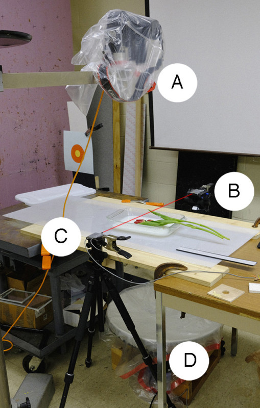
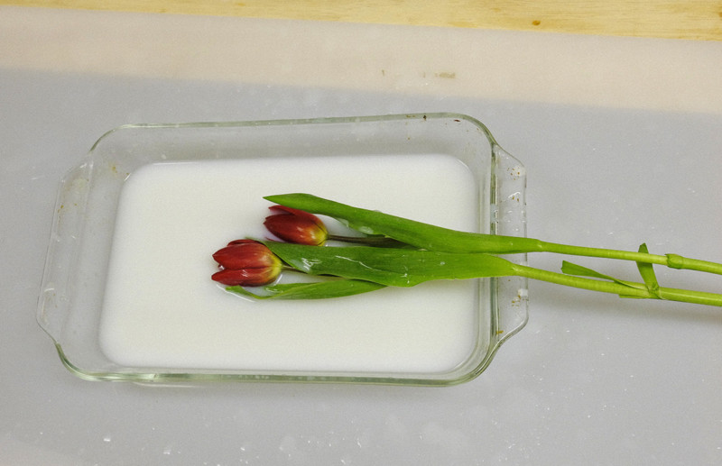
The flowers were held horizontally about 8 inches from the milk pan. Once the camera’s shutter was opened, the flowers passed through the IR beam to trigger a delayed strobe placed under the table. Reflectors were used to provide adequate fill lighting and were held above the pan to reflect light into the subject. One student controlled the camera via tether while another student moved the flowers, this allowed for multiple shots to be taken in quick succession with relative ease. Images were captured in total darkness so flower positioning was done prior to each sequence of shots.
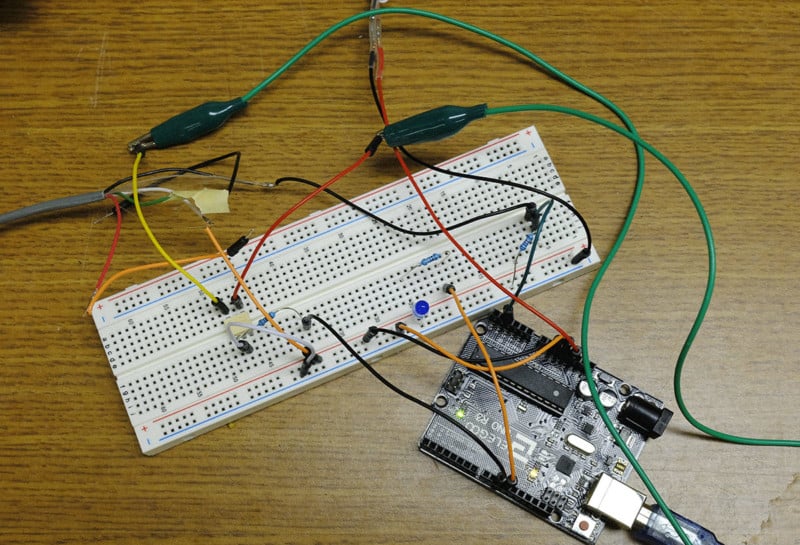
First, we will be talking about the physical system we created. The flash in this system is triggered using an infrared laser and detector.
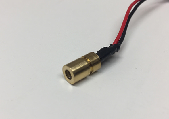
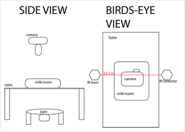
The emitter and detector are placed on two tripods across from each other, with the beam from the emitter crossing slightly above the surface of the milk container. The laser beam must be properly aligned with the detector in order for the trigger to work correctly. This was done by fitting a small piece of paper around the detector; this enables easy viewing of the beam. The beam can then be adjusted to align with the detector. Once aligned, the beam between the emitter and detector can be used as a trigger. When the beam is broken, the flash triggers. The laser used in this system has a wavelength of 780 nanometers. This ensures that when the exposure is taken, the infrared light cannot be seen in the image. Here is a diagram of what our set up looked like:
Here is a circuit diagram detailing how ours was set up:
The circuit schematic is shown below:
![]()
The IR phototransistor is the detector for the IR laser beam. The analog input pin on the Arduino is used to detect the signal from the laser. If the laser hits the detector the signal on pin (A3) is approximately 5 volts. When the laser is blocked pin A3 goes to zero volts. The analog pin is read in values from 0 to 1023. Due to the laser not being matched to the exact sensitivity of the detector the values never go from 0 to 5 volts. The students just read the analog values from the pin and adjust the code accordingly. In this system, a blocked beam went to a low value so the code uses a 120 value from the analog pin to trigger the flash sequence. It should be noted that this setup could be easily modified to use an IR LED instead of the laser. This activity was designed to give the students some experience using an IR laser.
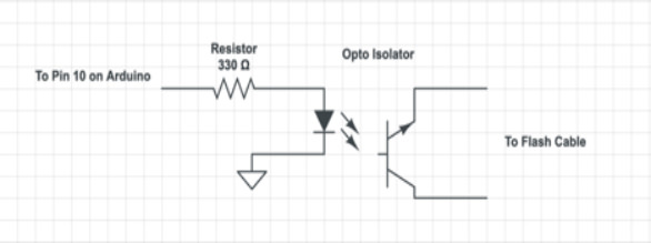
The optoisolator is used to isolate the flash unit from the Arduino electronics. The optoisolator is very fast and is the standard circuit for triggering flash units from a microprocessor like the Arduino.
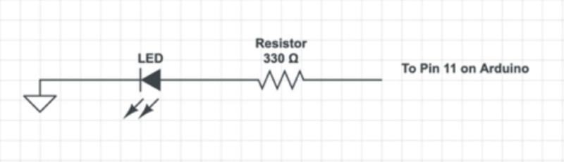
This schematic shows the LED light that is used to detect if the laser is blocked. This simple circuit is very important for alignment of a beam that is invisible to the human eye.
The program starts with the setup function, which declares that an LED and a flash are going to be used as outputs and sets them both to go off. The LED is for testing whether the IR sensor is working and the flash is what is going to be used to provide light to the image. The loop function, which is continuously repeated, is set up so that whenever the IR detector is reading at less than 120, the LED and flash are turned on and then off. The LED and flash are only on for 10 milliseconds. Afterward, there is a delay for 5 seconds to make sure the flash does not repeatedly go off immediately. Here is the exact code we used during our shoot:
/**IRLaserTimingForFlowers.ino
*
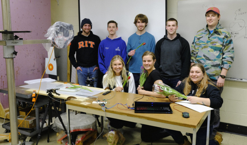
* Authors Morgan Ravenscroft, Stephen Rinaldo, Ashley Crichton, Tyler Wolstenholme, Patrick Damiano. Danny Heitmann, Kristina Kaszei
* Date created: 2/11/2019
*/
#define LED 11 //led is on pin 5
#define analogPin 3 //reading from phototransistor on analog pin 3
#define flashPin 10
const int flashTime=5000;// time it will wait before the next flash
const int pauseTime =10; //time it will wait between checks and between turning flash on and off
const int afterPass =65; //time between the IR laser being broken and the flash being fired in milliseconds
int val; //integer value called val used to read analog pin 3
void setup() {
pinMode(LED, OUTPUT); //Tells that pin 5 is used for an output
pinMode(flashPin, OUTPUT); //Sets the flash pin as an output
digitalWrite(LED, LOW); //Keeps LED off at start
digitalWrite(flashPin, LOW); //Flash starts off
}
void loop() { //Put your main code here, to run repeatedly:
val=analogRead(analogPin); //Analog reads val from 0:1024 on analog pin 3
if (val<=120){ //If the analog pin is read to be less than 120 delay(afterPass); //Delays for a time after the subject passes the infra red digitalWrite(LED, HIGH); //Turns on led digitalWrite(flashPin, HIGH); //Activates flash delay(pauseTime); //Keeps led on digitalWrite(LED, LOW); //Turns LED off digitalWrite(flashPin, LOW);//Sets flash to be ready to activate delay(flashTime); //Delays to allow for flash not to go off repeatedly } delay(pauseTime); //Delays to allow for read to be reset }


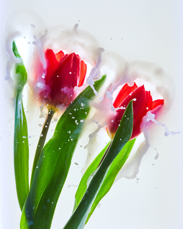
We had a lot of fun working on this shoot and we hope you are all inspired to do your own.
About the author: Ted Kinsman is an assistant professor of photographic technology at the Rochester Institute of Technology. He teaches advanced photographic technology, light microscopy, and macro photography courses. Kinsman specializes in applying physics to photography. You can find more about him and his work in his faculty profile and on his website.