Glass in the Path: Why Using Adapters May Hurt Your Image Quality
NOTE: This is a Geek Post. If you aren’t into geeky photo measurements, or into adapting lenses from one brand of camera to another, you’ll not be interested.
A year or two ago, I wrote a blog post where I basically showed lenses shot on adapters on other cameras aren’t acceptable for testing. If you run them through Imatest the results aren’t accurate. I suggested that reviewers shouldn’t test lenses on adapters, although obviously adapters are a great way to use interesting lenses to take pictures.
More recently, in online discussions about why certain lenses weren’t working on certain cameras, I brought up the fact that sensor stacks, the various layers of glass in front of the sensor containing AA filters, IR filters, etc. would be contributing to this problem; that there was more to it than just adapter irregularities. Most people thought that really wasn’t having an effect, though, so I forgot about it.
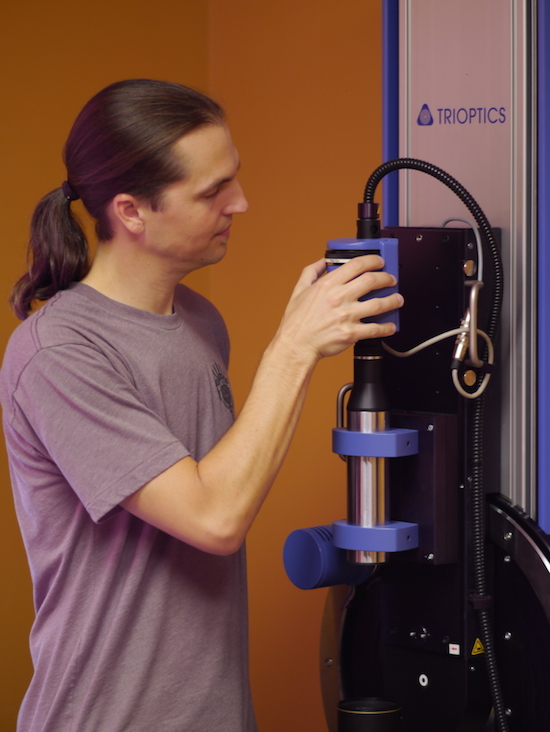
Yesterday I got a dramatic rude awakening that made me return to this train of thought and do some investigation. The way it happened was simple enough. Dr. Brian Caldwell, the guy who designed the Coastal Optics 60mm Macro, the Metabones Speedboosters focal reducers, and lot of other cool lenses came to visit. I’ve had the pleasure of knowing Brian for some time, but I will have to admit his visits (like those of several others) have become just a bit more frequent since we got our MTF bench up and running.
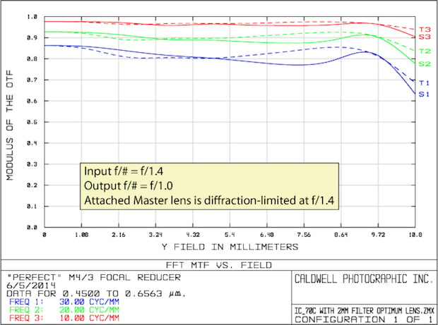
Brian had brought a prototype of his latest focal reducer. He told me it was so good that it clearly improved the MTF of full-frame lenses while increasing their aperture when mounting them to m4/3 cameras. He also brought the computer generated MTF graphs showing what it should do, which was pretty spectacular.
Well, we really couldn’t wait to play around with that, so we all gathered by the cheerful glow of the Imagemaster MTF bench and mounted a Zeiss Otus 55mm f/1.4 on it for a test run. As expected, the Otus generated very nice MTF curves.
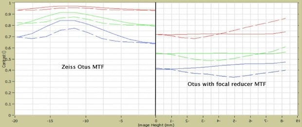
Then we mounted the focal reducer on the Otus, adjusted the MTF bench for the narrower depth of field and greater aperture, and tested the combination. The results were absolutely awful. We rechecked all our settings and ran it again. Awful. We tweaked some settings. Awful. Here’s an example, of the same side of the same lens with and without the focal reducer straight out of the MTF bench. (I’ve flipped the MTF of the reducer to make it easy to compare, which is why the numbers are backwards.) We repeated this with several lenses and it’s about the same every time.
The room became really quiet. Then Brian jumped up and said, “Filter stack — the machine doesn’t have a filter stack.” What he meant was that every digital camera has several pieces of glass in front of the sensor. The light leaving the rear of the lens has to pass through this glass before arriving at the sensor. Brian’s design (like that of most lenses) accounted for this filter stack in the optical formula. Since this adapter is designed for micro 4/3 systems, which have an optically thick stack, no glass in the path might be the issue.
So we found a couple of 2mm pieces of optical glass, mounted them in the optical pathway between the lens and the MTF sensor, and ran the tests again. Suddenly the Otus — focal reducer combination was amazingly good. As Brian had promised and predicted, it was a bit better at f/1.0 than the Otus was at f/1.4 (over a smaller angle of view, of course).
OK, But What About Regular Lenses?
The MTF results with Brian’s Perfect focal reducer were ridiculously dramatic, and to be honest I didn’t believe the glass could make that much difference. Brian often speaks to me in English because it’s a common language we both understand. But when he gets excited he lapses into his native Theoretical Optical Physics, which I can barely follow. Luckily, he had brought his colleague Wilfried Bittner, who speaks both Theoretical Optical Physics and English (although his native language is German). With Wilfried’s aid as translator, I’m pretty sure I understand that at effective apertures under f/1.4, glass in the optical pathway have a huge effect on spherical aberrations, which are apparent even in the center of the lens’ field.
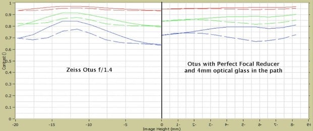
But I still wanted to see if this had an effect on even normal lenses. So we put another copy of the Zeiss 55mm f/1.4 on the Imagemaster and tested it. (This is a single lens test so you’ll notice a slight tilt. Every lens has a slight tilt when measured at this way-beyond-pixel-peeping level.) Then we put our 4mm of optical glass in the pathway. The image below shows the MTF comparison for the Otus when tested with no glass in the optical pathway compared to same lens with 4mm of optical glass in the pathway. Red, green, and blue lines are for 10, 20, and 30 line pairs/mm.
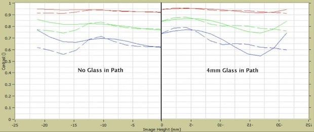
The MTF is better now higher in the center, but there is more astigmatic off-axis. (I was surprised at the on-axis effect, but Brian tells me that the glass in the path creates on-axis spherical aberration that could affect center MTF on wide-aperture lenses.) But then we realized this is a Canon lens, not an m4/3 lens. Canon cameras, as best we know, have about a 2mm filter stack. So we reduced the glass in the path to 2mm and ran the test again.
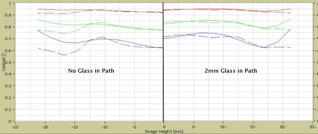
The 2mm result does seem a bit better over all, compared to the 4mm.
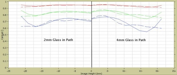
We repeated this for a couple of other Canon wide aperture lenses and found similar results. The MTF bench results are better when there is a 2mm piece of optical glass in the path between the rear of the lens and the bench’s sensor.
So This Should Work the Other Way, Right?
OK, so if micro 4/3 lenses are expected to have a thick sensor stack, and to be at their best, lenses have to be designed to take this into account. Canon lenses supposedly have a medium-thickness sensor stack, and lenses designed for them seem a bit better if we put a thinner piece of glass in their optical path. What about lenses designed for little or no sensor stack? Actually, it’s already been shown they don’t do well on camera with significant sensor stacks. Panavision has made premium lenses for their film cameras for many years. Recently they’ve released their Primo V series of lenses, which are their Primo lenses modified, according to their website to “ eliminate coma, astigmatism (vertical and horizontal focus differences), and other aberrations caused by the extra layers of glass in digital cameras.” U. S. Patent application 14/024,578 describes adding additional optics to the existing lenses to correct for the glass in the imaging pathway, that is between the rear of the lens and the camera sensor.
But seeing is believing, so we got a good Leica lens (a 35mm ASPH Summicron) and tried the same tests. Even today, Leica is known to use much thinner filter stacks (1mm or so) than the other camera manufacturers. So putting optical glass in the imaging pathway of an older Leica lens should make it worse.
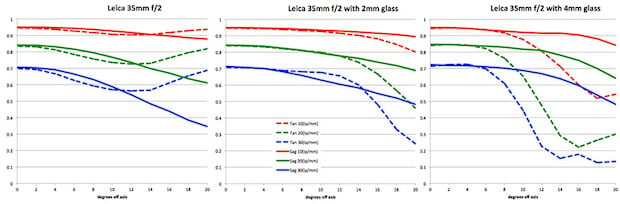
The Canon mount lens got a bit better with 2mm of glass in the optical path. The Leica 35mm ASPH had an odd reversal of astigmatism with sagittal lines improving a bit, but tangential lines getting much worse. Overall I’d say it wasn’t better or worse, just different. With 4mm of glass in the optical pathway, though, the Leica clearly gets worse.
Conclusions
The things I’ve brought up today aren’t unknown, although they aren’t widely talked about. Bruno Massett had an excellent discussion about the theoretical implications almost a year ago in Mike Johnston’s The Online Photographer. Lens designers plan for the thickness of the sensor stack, and others have made corrective lenses to allow very expensive lenses developed for film to be used on digital cinema cameras.
Obviously this isn’t an exhaustive test using a large series of different lenses. The purpose of this post is simply to serve as a demonstration that the thickness of the sensor stack does have an effect: if a lens is designed for a certain thickness sensor stack, it may have issues when shot on a different thickness sensor stack. I figured if I was surprised, some of you would be, too, so I wanted to post this now.
Real-World Implications
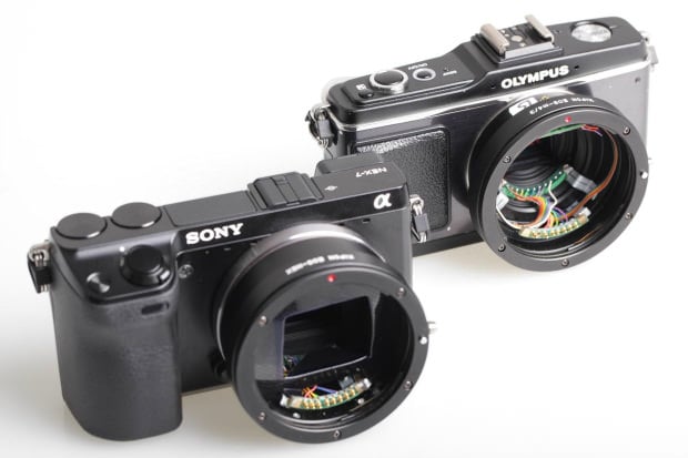
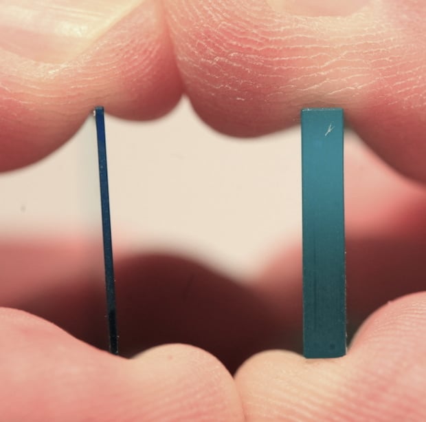
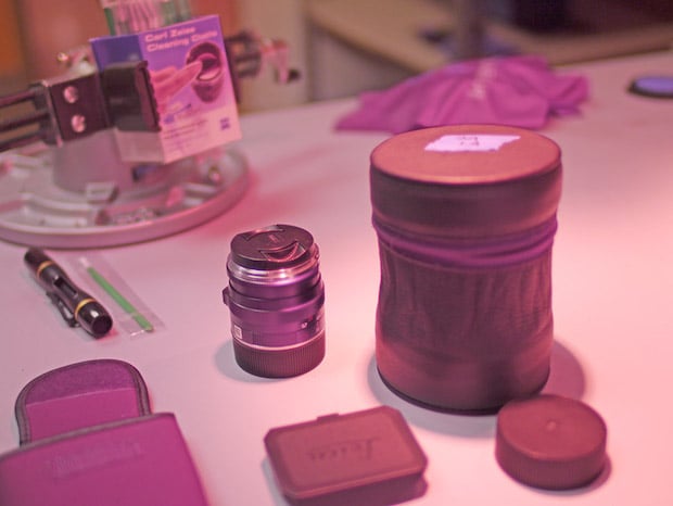
We don’t know which lenses on which cameras will be most affected. In order to start making some generalizations, a good database of sensor thickness needs to be made public. I’ve only been able to find references to a few. We know Leica is thinnest and I was told micro 4/3 was the thickest at 4mm. I didn’t believe that, so we took a GX1 apart. As you can see from the first picture, it is, indeed very thick and I can confirm it’s a bit over 4mm.
The extra good news is we now have a micro 4/3 camera with absolutely no glass in front of the sensor at all and a really nice piece of 3mm thick cyan glass for a conversation piece. The camera no longer focuses to infinity, of course, but it takes nice pictures in UV/IR/Visible light spectrum, at least up close. (I know what you’re thinking: but no, we didn’t start this article just so we could make a glass-free GX1.)
I hope to have at least a moderately complete database of sensor thicknesses done and published by early next week. We’re doing some disassembly here to measure sensor glass and have sent some cameras off so the glass can be measured optically. Optical thickness may be somewhat different from measure thickness since different types of glass might be used. (If you have some knowledge in this area, I’d appreciate an email or comment post. You might save a camera.)
Testing Implications
Even testing on our optical bench, corrections may be needed for lenses designed to have a certain thickness of glass between their rear element and the sensor. So we’ll be going back to doing more testing there, too. I suspect, for example, that the numbers I posted in last week’s 50mm article might actually be a tiny bit lower than reality for the Sigma Art and Zeiss Otus lenses.
Or perhaps not. Obviously this is a new area and we’ll have to run lots of copies on the bench, and correlate them with Imatest or other complete systems measurements before we know for sure.
Sensor stack thickness might end up being no big deal. But hey, if it’s important enough for Panavision, it’s important enough for me.
About the author: Roger Cicala is the founder of LensRentals. This article was originally published here.