How I Repaired a Broken Mamiya RB67 Medium Format Camera
I had the Mamiya RB67 and Pentax 67 on my medium-format wanted list for many years now, but I simply could not justify the price tag or bear the unfortunate realization that either camera would sit lonely and unused on a shelf. That all changed in December 2022 when I decided to grab a non-working RB67 as a Christmas Present for my eldest brother.
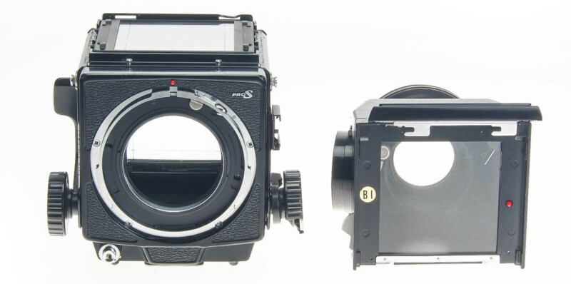
Buying the Mamiya RB67
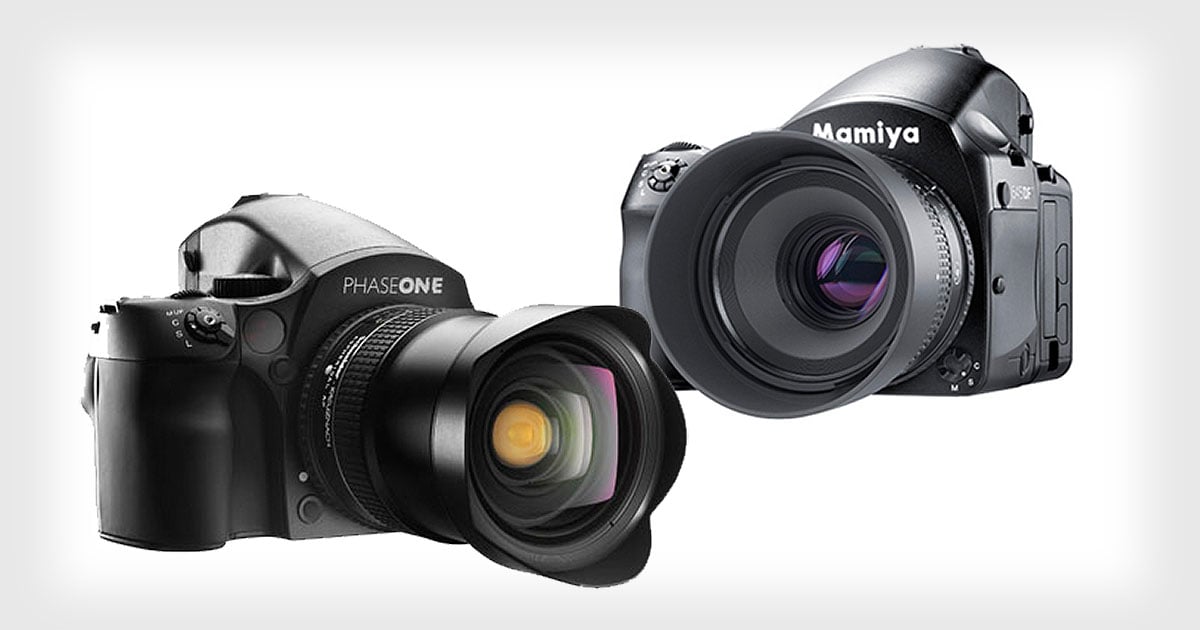
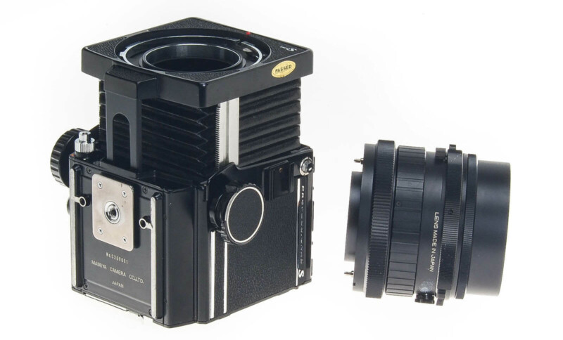
The Mamiya RB67 was first introduced in 1970, 53 years ago. The RB67 was manufactured until 2009-2010 when whatever left of Mamiya was sold to Phase One. Considering how little changed in design over those decades, that is an incredible run for a complex mechanical device like a film camera, let alone any consumer product.
It is fair to say that a majority of the RB67s available right now were produced in the late 70s-80s. This means the average RB67 you’ll find has 30-to-40-year-old light seals! Even if you find a mint example, the chances of disintegrating light seals and bellows with light leaks are very high. If you want any camera of this vintage to work seamlessly, you have to set aside some time and caress the camera back to working condition.
With this in mind, I simply could not bring myself to drop ~$500 on any RB67 in any condition. Considering there are no nearby film stores that stock old cameras for perusal, I took a gamble and made an offer on a broken RB67 from National Camera Exchange. I have purchased many cameras from them in the past and I personally rank them a close second to KEH for used camera gear. Luckily, they took my $150 offer, and off I went searching for parts and a service manual.

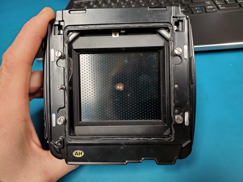
I took a gamble. The listing described a stiff focus knob, separation in the lens elements, an unknown viewfinder exposure meter, and the slightly less desirable 220 film back, with large parts of the outer foam seal missing. Most of these problems would deter any sane person from purchasing this camera.
However, I was banking on several things. If the focus knob was stiff, it’s likely that the camera was not used very often and the front bellows mostly stayed in a closed state. Ironically, the external condition of the camera was mint. The body paint did not have any scratches or chips anywhere, leading me to conclude that the camera sat for a while after the focus knob damage occurred.
A big deciding factor was the clean and even folds shown in the bellows in the listing photos. No creases or damage to the corrugations were evident. This is great news. The foam seals were in need of replacement anyway, so I did not mind, and many folks have had success using 120 film in a 220 back.
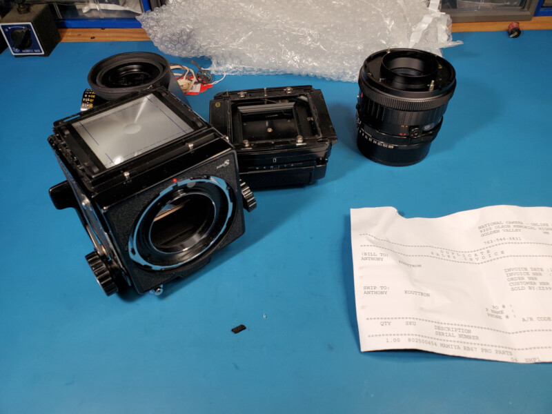
An Initial Inspection of the Camera
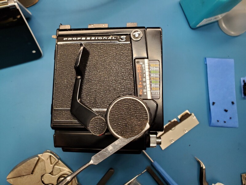
With the camera on my workbench, my initial inspection was not very promising. A small shard of what looked like safety glass fell out of the camera, large bits of foam from the mirror fell out and I noticed that I could not inspect the film back because the dark slide was not present. In addition, more seals were absolutely toast, as the rear of the camera body was devoid of all foam seals, with just traces of adhesive left behind.
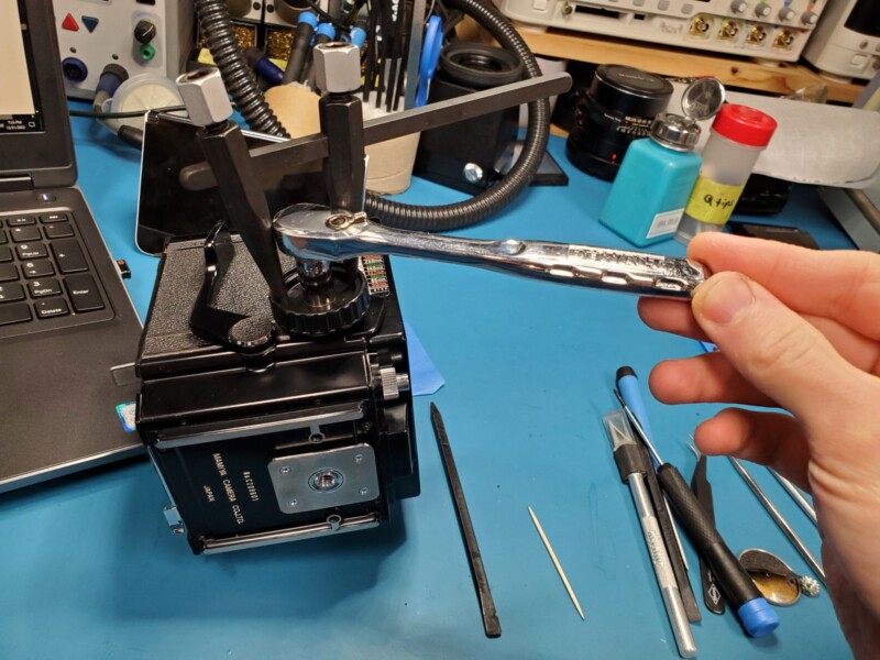
The most alarming problem was the focus knob being stiff. The knob was busted as expected, but the amount of force necessary to rotate the knob was considerably more than I hoped. I needed to torque the focus knobs on both sides of the camera to just move the focus plate mere millimeters to expose the bellows.
At this point, I was really concerned that the focus rack or pinion was damaged and teeth were mushroomed over or missing. However, after studying the service manual and observing other photos, there was a good chance that the parts under stress were brass. Brass is a very malleable material, and if the camera took a fall as this one clearly did, it’s likely the brass part could be carefully massaged back into shape.
Worst case, if I could not find replacement parts, I could machine something out of brass with my lathe.
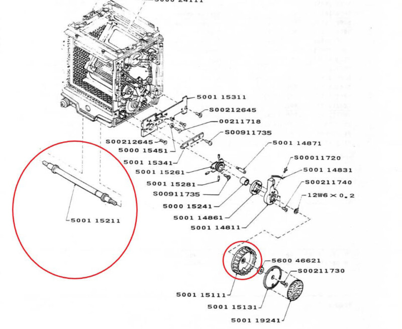
As you could have guessed, there are no parts available for the RB67! This was a bit of a letdown and put a damper on the repair process, as I started looking for a second repair camera to harvest parts from. Out of sheer frustration with eBay prices, I just decided to teardown the camera and inspect the focus mechanism before I went any further. Luckily, the service manual is incredibly useful and contains all the diagrams and procedures on how to teardown, service, and adjust the camera – almost unheard of in the year 2023!
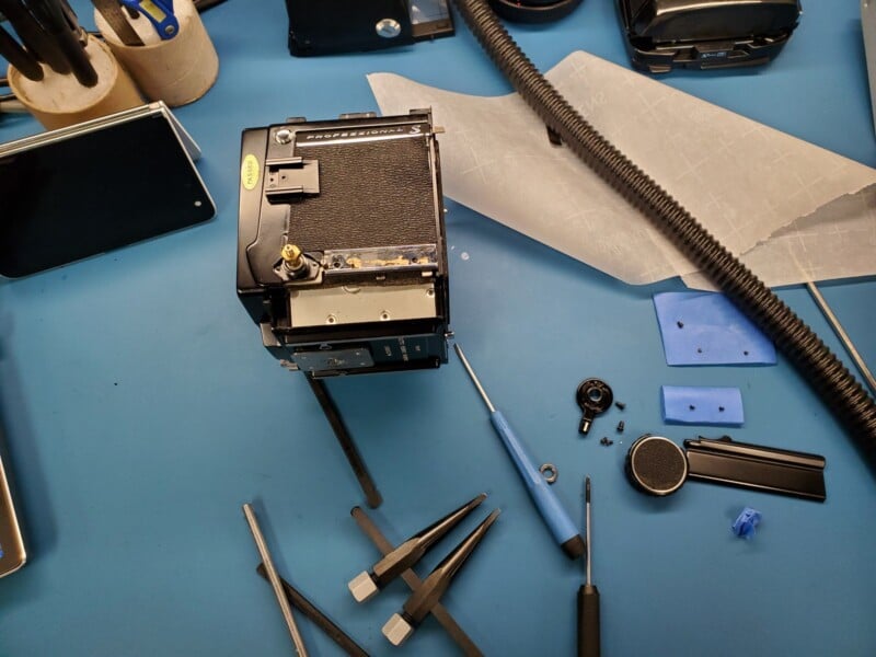
The disassembly process is straightforward enough: remove the focus knob first, then the bottom plate, the cold shoe screws, the side panel leatherette, a few screws in the side panel, and finally the shaft knob collar.
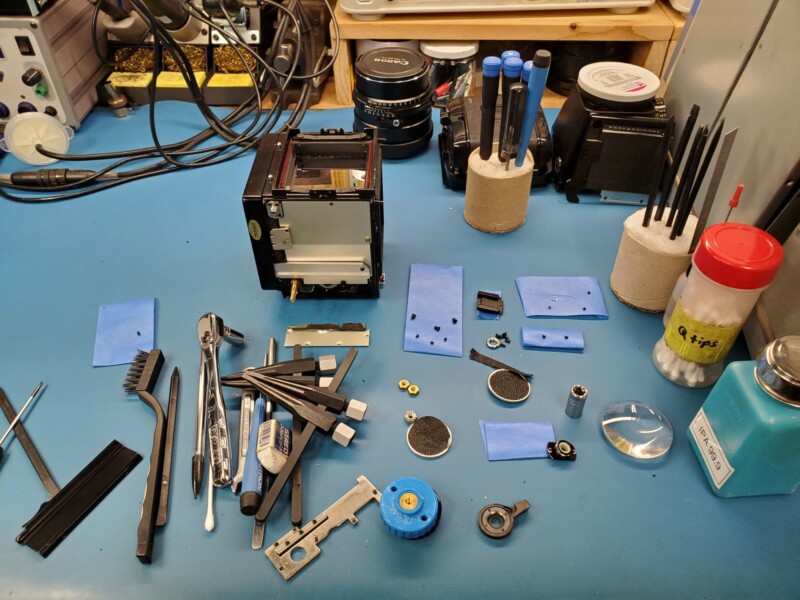
Before I dig into any camera, I like to use tape to keep track of where each screw lived on the camera body. It is convenient and practical, and it does not discriminate against aluminum screws like a magnetic mat.
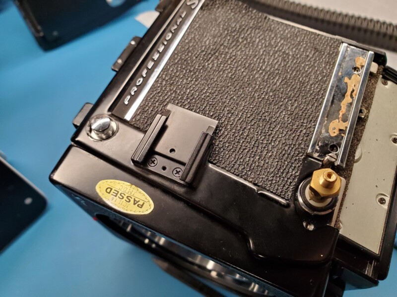
I started from the broken knob side and since it was in such poor shape, I did not have to remove the leatherette covering the knob. The circular aluminum backing plate simply unscrewed from the knob face. The retaining nut was already loose and the knob came off with ease.
There are two tiny black machine screws that hold the shaft collar to the body. Additionally, there are two cheeky screws hidden behind the cold shoe spring plate. To dig any further, the bottom leatherette rectangle needed to be removed and the top right corner of the leatherette needed to be peeled back to reveal more screws. The side panel is a bit fiddly to remove as you have to rotate it and pull it back for the panel to come loose.
Something missing from the service manual is how to remove the leatherette that is glued everywhere on the camera. Luckily, the same procedure used in removing leatherette from modern-day cameras applies here. You just need to use moderate heat and thin, yet blunt pry tools. Plastic pry tools work well with low heat, but thin metal pry tools are more reliable if additional heat is needed. I used a mixture of both and then painstakingly nudged my way under the material and wiggled around to remove the material from the decades-old adhesive.
The process is about 20x slower than with modern cameras as the adhesive Mamiya used barely responds to heat and leaves a terrible yellow film behind on the panel. You must tread lightly here as even square-edged plastic spudgers can tear through the leatherette. I cannot stress enough: use pry tools with rounded edges! As you can guess, the leatherette is no longer available. You can probably cut your own, but I opted to not spend the time researching a period-correct leatherette material, and leave the camera as stock as possible.
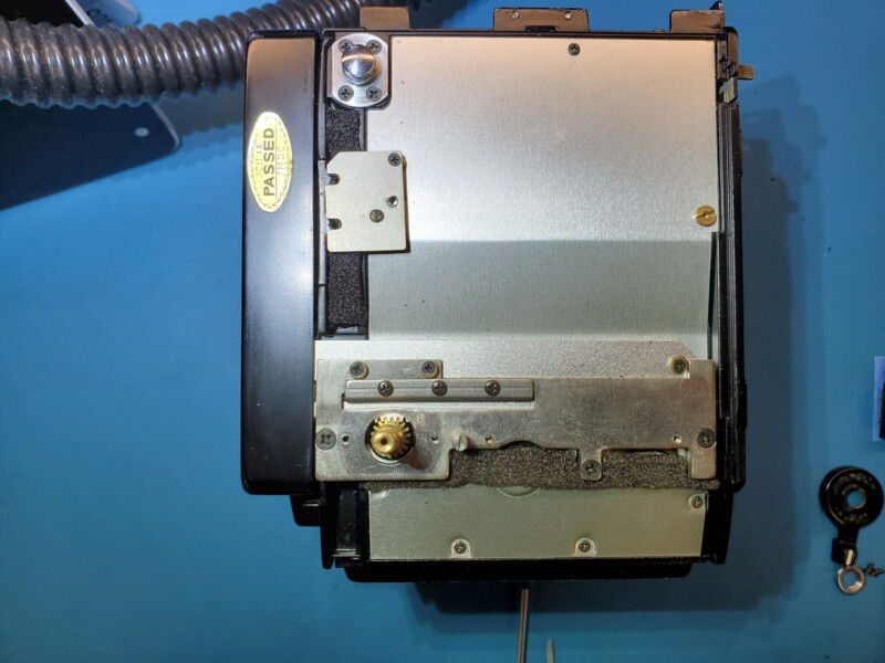
With the side panel set aside, there is another metal bracket that obstructs the focus rack: the metal focus guide. Removing three Phillips screws reveals the sorry state the guide was in: bent and mangled. Being composed of soft stamped steel, the guide was not hard to convince back into shape.
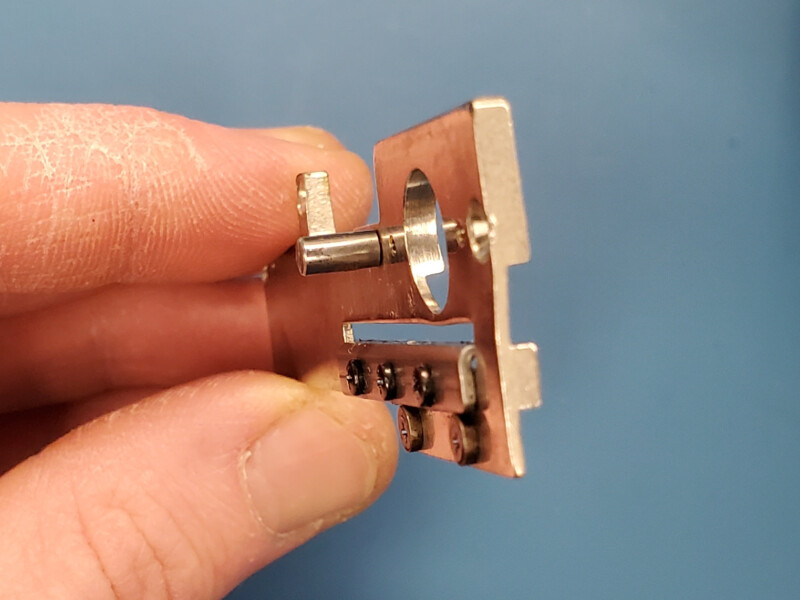
The Knipex Plier Wrenches are a perfect match for this job. Each jaw is parallel to the other, making them invaluable for simple metal work and bending operations, besides the marketed bolt and nut removal. They are incredibly handy tools and I recommend them for anyone’s tool collection, even though they command a premium. Speaking of useful tools, I usually print out a service manual when disassembling a new-to-me device, but my surface duo was surprisingly practical as an alternate solution. Being able to zoom in and easily scroll through a 100+ page PDF all while allowing me to adjust the viewing angle was priceless. It’s too bad the duo is an incredibly fragile device, but more on that another time.

With these two parts removed, the focus rack is now in plain sight and allows you to better observe the state of the focus mechanism. Somehow, none of the teeth on the steel rack were damaged. The edge of 3 teeth looked slightly more used than others, but it was such an insignificant bit of wear that a diamond file easily cleaned them up. More importantly, all of the teeth were still square to the profile of the rack, which is excellent news.
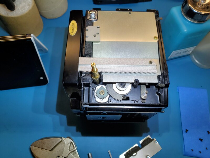
Since the rack was undamaged, this leaves the focus rod and pinion to bare the weight of the damage. In the RB67, the pinion is not a traditional separate gear. Instead, the pinion is broached into a protruding profile on the solid brass focus shaft that runs the width of the body and connects to both focus knobs. The removal of the focus collar gives a full frontal view of the pinion, but it is still very much captured by the opposite side of the camera.
On close inspection, the left face of the pinion teeth looks great! It is hard to draw conclusions about the opposing side of the pinion so the entire focus shaft must be removed. In order to free the focus shaft, both knobs must be removed from the camera along with both focus collar mounts.
The undamaged focus knob required a lot of finesse to remove without damaging anything.
First off is the leatherette cap using the same technique as above. Behind the skin are a circular aluminum plate and a small brass screw. Make sure to unscrew this screw perfectly square with the screw head as the screw offers little purchase to ease in the removal process. Apply a lot of force, turn, and it should come out. If you just blindly unscrew it, you will be in for a bad day.
Next up is an 8mm brass nut, but you will need a way to prevent the knob from turning while you loosen the nut. I opted to use the round tip circular profile lens spanner wrench from SK Grimes. It is a simple yet invaluable tool for lens repair and worth its weight in gold for tasks like this. Finally, you can unscrew the knob.
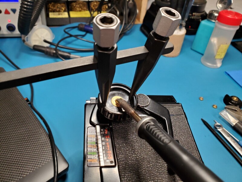
These focus knobs are Bakelite, making them incredibly brittle if torque is unevenly applied. There are also many casting lines on the surface of the knob, which is a bit unsettling as I don’t have a replacement knob and parts are unobtanium. I made my life a little easier and pressed a 120w soldering iron tip against the focus knob brass insert for about a minute, just in case there was thread compound used during the original assembly.
With no knob on the opposing side, the only way you can safely remove the knob is to first place the camera on its bottom. Grab the knob, apply downward pressure on the focus shaft so the focus pinion mates with the rack, then unscrew. This way you don’t accidentally damage any teeth.
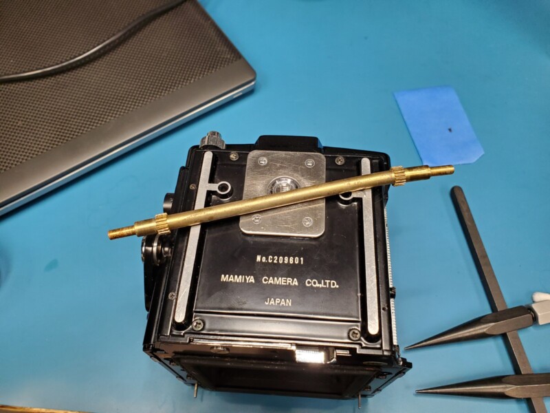
As expected, the focus rod was damaged. Oddly enough, the teeth of the pinion gear were unscathed. The gray marks observed were just old grease and a tiny bit of wear. There were no indentations in the pinion teeth or stepped geometry. All teeth were still square and none of the edges were mushroomed over, just the rod was badly bent. This is the best-case scenario.
I was debating machining another rod with my lathe, but then I remembered that brass is quite malleable and I could probably just make the rod rotate true again.
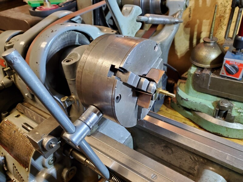
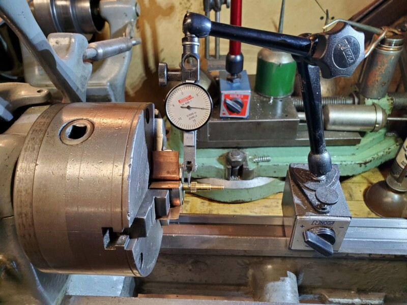
All that was needed was the lathe, a three-jaw chuck, copper shims, a machinist arm or “magic arm” and a dial indicator. The most critical part of this technique is to clean any traces of metal chips from all jaw teeth and use a soft metal shim stock on the three jaw chuck so as to not deform the brass focus rod and cause additional damage. I choose copper for the job.
This procedure was a piece of cake for my Southbend 9. When it came time to tighten the chuck with the chuck wrench, only a small amount of torque was applied to the wrench, enough so that the brass rod did not spin after my attempts by hand. I’d say I rotated the wrench just a mere few degrees. I am mentioning this because the part diameter is small and chuck wrenches allow you to apply a lot of torque on a part, enough to make round brass stock triangular.
Note: No power was applied to the lathe for this procedure, as the lathe was only used for fixturing and observation. It is bad practice to leave a chuck wrench installed in a chuck. It is only displayed here to demonstrate the size of chuck wrenches and how much torque you can apply to a part.
I mounted the rod in the chuck, making sure the pinion cleared the jaw teeth, and mounted the magic arm nearby with a dial indicator directly above the center of the focus rod axis.
It is imperative that the dial indicator is adjusted perpendicular to the rod or else you are not going to obtain any useful measurement from rotating the rod. I used a “0.0005in” or 5-tenth dial indicator not because I was trying to be super accurate, but because the tip on the indicator was small enough to clear the 3 jaw teeth and the pinion without any catastrophic interference.
As shown, the rod was incredibly off-center. If you notice, I started by measuring the rod before the pinion, not between the pinion and the threaded part. That portion of the rod was deformed from my initial foolish attempts of bending the rod before completely disassembling the camera.
Since brass is so malleable, my weapon of choice was a piece of hickory, or simply a broken claw hammer handle. I rotated the three-jaw chuck with my left hand and watched for patterns in the dial indicator.
The dial indicator gives you an idea of change over rotation. By rotating the chuck back and forth a few times you get an idea of where the high spots and low spots are based on where the pointer on the dial stops and changes direction. When the pointer changes direction you have found one of the extremes.
Rotating back and forth helps you find the other extreme and you can get a good ballpark of how out of round the part is by counting up the gradations on the dial face between the extremes. These gradations usually represent thousandths of an inch. In the case of my dial indicator, they represent 5 ten thousandths of an inch. That may sound confusing, but just think of every larger marking as a thousandth and every shorter marking between as 5 ten thousandths or half a thousandth.
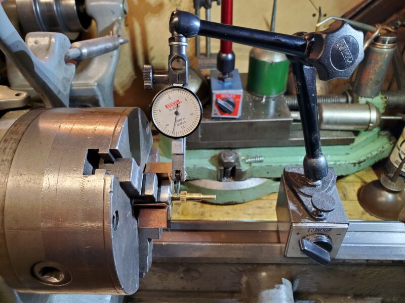
Since brass is very soft, it can be persuaded to bend with even the slightest bit of force. Rotate the chuck to one of the extremes and tap lightly with the wood handle. You will see the needle change on the dial indicator. Rotate the chuck again and observe the dial indicator. You may see an increase or decrease in the gradations between extremes. If you observe a decrease between the extremes, you have been hitting the correct side of the brass rod.
Continue to lightly tap at that location of the extreme and observe the dial indicator until you minimize the amount of runout between the two extremes of measure. If you happen to strike the wrong extreme, the number of thousandths out of round will increase. Simply tap near the alternate extreme measurement and you should begin to see an improvement between your extreme measurements.
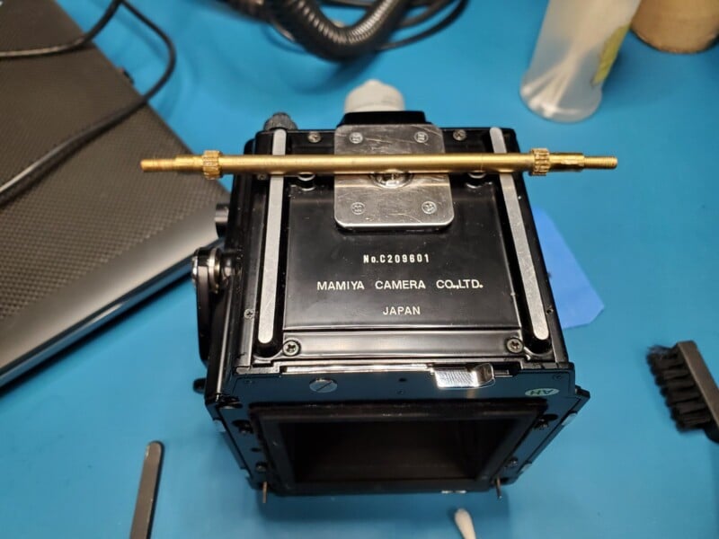
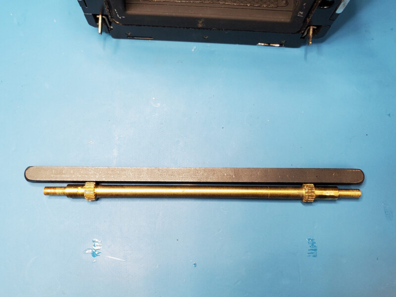
Tapping the end of the brass rod lightly with the wood handle several times reshaped the part back into a useful rod. I chose to strike the brass rod between the threads and the pinion to prevent any potential damage to the important geometry.
To be clear, when I mention “tapping” I truly mean tapping. I barely applied any substantial amount of force on the brass shaft. The weight of the wood handle applied most of the force, I did not use any additional hand strength to strike the brass. This is the level of caress you must use when performing this task. A little goes a long way.
It’s easier to use small taps, rotate the chuck, observe the dial indicator, and tap again than blindly use one large strike. I was able to get the rod within 7 to 8 thousandths of an inch, which is frankly not too bad when considering how bent the shaft was originally. This is the repaired brass focus rod against the 1/4in square stock used in my SK Grimes lens spanner. Gillette would approve.
With the shaft as straight as it’ll ever be, I shifted my attention to the elephant in the room: the broken focus knob. I took some measurements of both focus knobs and fired up my native CAD program. The broken knob actually helped in the process as I was able to take cross-sectional measurements without having to use more complicated measuring techniques to find out inner wall thicknesses.
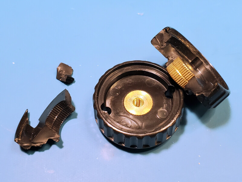
Luckily, the original Bakelite knobs are produced in a very straightforward manner: a brass insert centered around support material. If this terminology sounds familiar to you, congratulations! That’s the solution to the broken knob problem: a brass insert in 3D-printed ABS. I broke away what was left of the Bakelite material, measured the outer diameter of the brass insert, and adjusted the CAD to allow for an interference fit during the final insert operation.
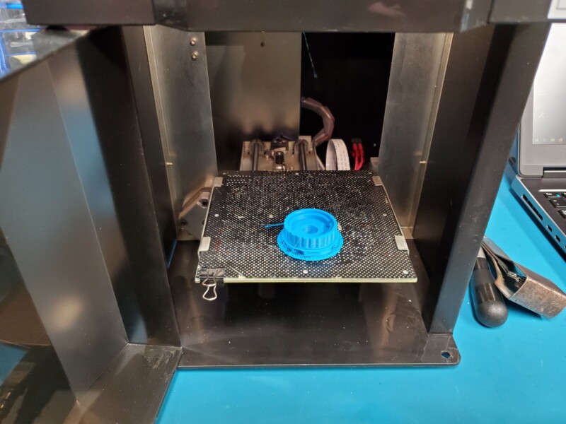
My little Up Mini printer did an excellent job printing the knob. The first knob came out a bit warped, but I soon found this was its way of informing me that the print bed was in need of deep cleaning. The next print came out stellar and was near identical to the CAD I designed, not an easy feat for FDM printing.
Just a few years ago, I began to accept parts coming back 20 – 100 thousandths of an inch off with local printers, but this one takes the cake in terms of accuracy and convenience.
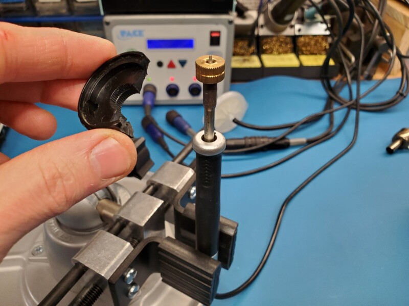
To make the final assembly process easier, I mounted my 120w soldering iron in my table vise pointing straight up in the Z-axis direction. To both stabilize and evenly heat up the original brass insert, I chose a small-diameter soldering iron tip with a large shoulder. I let the brass sit on the soldering iron tip for about 3 minutes to get the part nice and warm. I grabbed the 3D-printed part, lined it up to the brass insert as square as I could, and quickly pressed the parts together.

Once I saw the blue excess support material overflow from the top of the center of the knob, I knew the insert had successfully passed through the body of the knob. I quickly removed the finished knob from the soldering iron and let the final knob cool on my ESD mat. Once the part was cooled I removed the excess ABS material from the center.
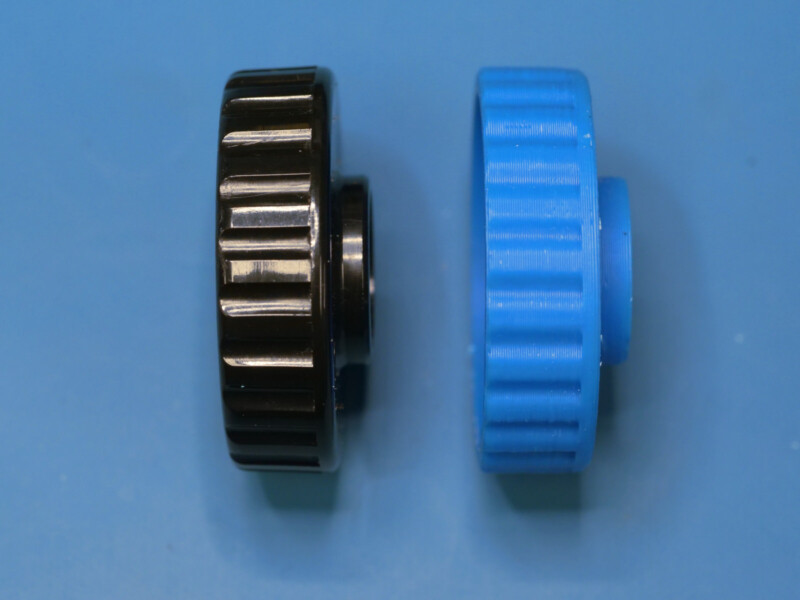
The final result was nothing short of remarkable. With some light sanding on the edges, the knob felt excellent in the hand. Choosing to print with 99% infill was likely overkill, but I do not regret the decision, as the newly formed knob has a similar weight as the original Bakelite knob and does not deform easily even when squeezed with all my hand strength. This is a very desirable trait because the last thing I want is for a knob to feel like it will fail with continued use. Here are the two knobs side by side.
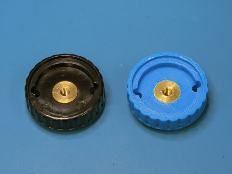
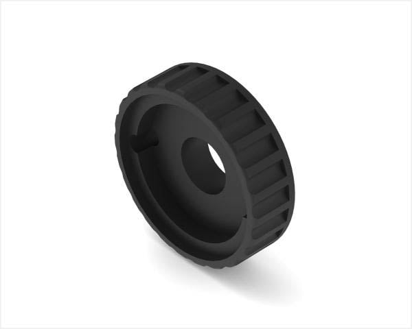
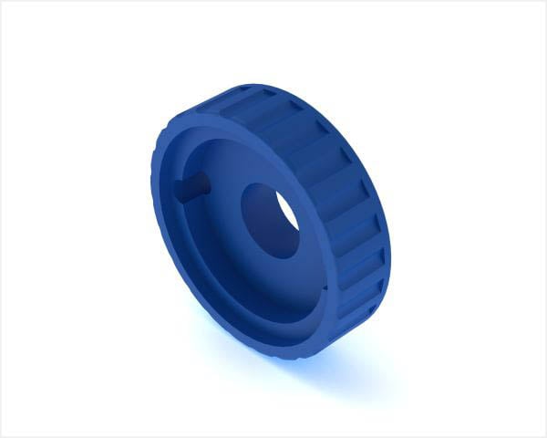
Sure the color blue is a bit odd, but frankly, who cares, I can always print one a different color. Mort importantly, now you can too! Here is the exact CAD of the RB67 knobs. There are two versions of the knob. One version is identical to the Mamiya knob, with the slight taper on the grip, and the second version has a square profile grip. I have provided the files in both .step and .stl. Enjoy!
RB67 Knob Original Download:
RB67 Knob Square Download:
With the knob situation straightened out, I went ahead and began reassembly. I did things a little differently and put the 3D-printed knob on the opposite side of the camera. Since this is an RB67 pro, the left-hand knob has a focus lock lever that torques against the inside of the knob. I want to prevent any premature damage to the 3D-printed knob and let the lever torque against the original Bakelite knob instead. This is probably an unfounded concern, as the ABS knob is likely more strong and more stable than the working Bakelite knob.
The biggest challenge with any reassembly is making sure you do not have leftover screws. Thankfully, this is where the service manual and tape really came in handy.
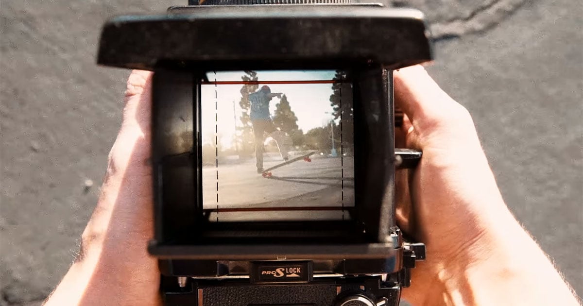
Well, the camera is all assembled and ready to go, but the viewfinder needs a little attention. A lot of folks really enjoy the convenience of the folding viewfinder, but everyone knows the chimney-style viewfinder is more comfortable and less fiddly.
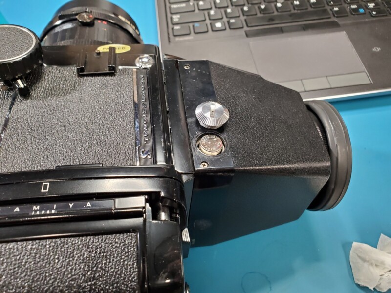
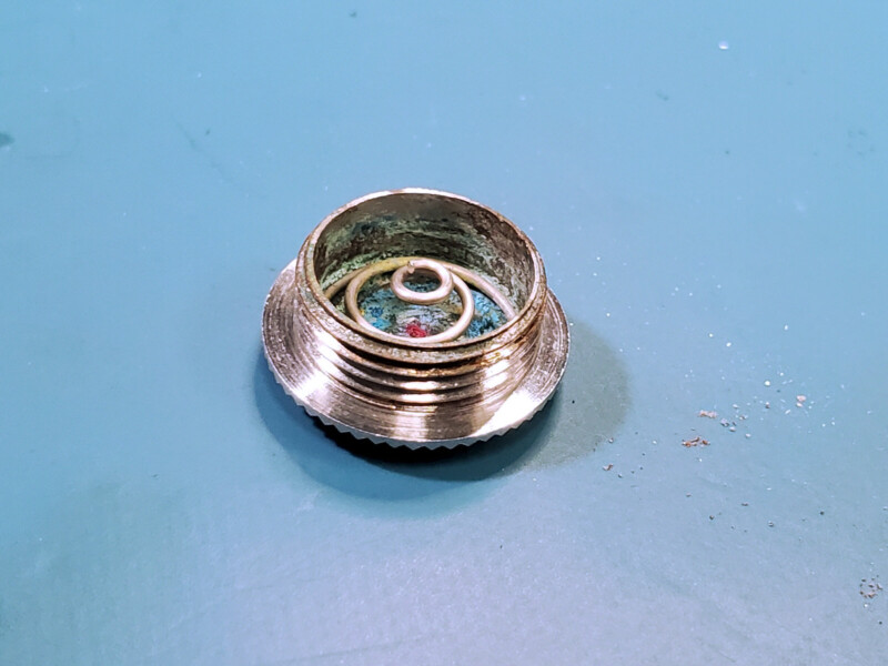
The chimney viewfinder has a primitive built-in exposure arm that runs on an SR44 button cell battery. Out with the lil bugger and in with the clearing agents and spare caliper battery.
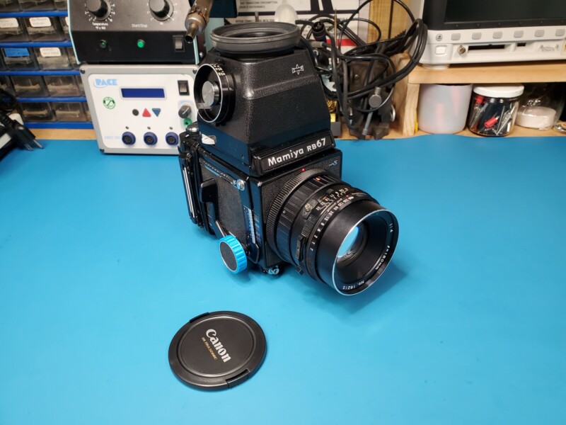
Now, that’s what I call a camera. Sure, I did not get the seals in time for the Christmas season, but that’s easy enough to apply with some toothpicks, alcohol, and patience. For now, a lonely, mistreated RB67 has been pulled off the streets and is almost ready for action once again. Thanks for sticking with me this far and thanks National Camera Exchange for not disposing of such a majestic camera!
About the author: Anthony Kouttron is the camera enthusiast, electrical engineer, and hobbyist behind the website Salvaged Circuitry. You can find more of his work on YouTube, Twitter and Instagram. This article was also published here.