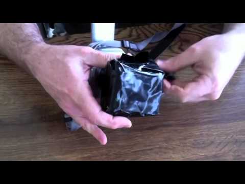
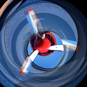
The Math Behind the Rolling Shutter Phenomenon
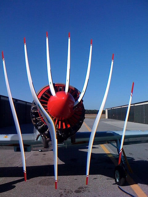
I remember seeing the photo above on Flickr once, and having my brain melt slightly from trying to figure out what went wrong.
The issue was the propeller was rotating as the camera detector ‘read out’, i.e. there was some motion during the exposure of the camera. This is an interesting thing to think about, lets have a look.
To illustrate, consider photographing a spinning propeller. In the animations below the red line corresponds to the current readout position, and the propeller continues to spin as the readout proceeds. The portion below the red line is saved as the captured image.
First, a propeller which completes 1/10th of a rotation during the exposure:
Some distortion, but nothing crazy. Now a propeller moving 10 times quicker, which completes a full rotation during the exposure:
This is starting to look like the Flickr image at the beginning. 5 times per exposure:
This is a little too far, things have clearly gone mental. Just for fun, let’s see what some different objects look like at different rotation speeds, from 0 to 1 rotation per exposure.
The same propeller as above:
A fatter propeller:
A car tire:
We can think of the rolling shutter effect being some coordinate transformation from the ‘object space’ of the real-world object, to the ‘image space’ of the warped image. The animation below shows what happens to the Cartesian coordinate grid as the number of rotations is increased. For small rotations the deformation is slight, as the number increases to 1 each side of the grid is moved successively towards the right-hand side of the image. This is a fairly complicated transformation to look at, but simple to understand.
Let the image be denoted by $latex I(r,\theta)$, and the real object (which is rotating) be denoted by $latex f(r,\theta)$ where $latex (r,\theta)$ are 2D polar coordinates. Polar coordinates are a natural choice for this problem due to the rotational motion of the objects.
The object is rotating at angular frequency $latex \omega$, and the shutter progresses across the image at speed $latex v$ in the vertical direction. At position $latex (r,\theta)$ in the image, the distance the shutter has moved since the start of exposure is $latex y = r\sin\theta$, and so the time elapsed is $latex (r\sin\theta) /v$. In this time the object has rotated a number of radians $latex (\omega/v) r\sin\theta)$. Putting this together,
$latex I(r,\theta) = f(r,\theta + (\omega/v)r\sin\theta)$
which is the required transformation. The factor $latex \omega/v$ is proportional to the number of rotations during the exposure, and parameterises the transformation.
To get some insight into the apparent shapes of the propellers, we can consider an object consisting of $latex P$ propellers where $latex f$ is non-zero only for $latex \theta = 2\pi/P, 4\pi/P \dots 2\pi = 2p\pi/P$ for $latex 1 < p < P$. The image $latex I$ is then non-zero for $latex \theta + (\omega/v)r\sin\theta = 2p\pi/P$ or $latex r = \frac{v}{\omega}\frac{2p\pi - \theta}{\sin\theta}$ In Cartesian coordinates this becomes $latex \text{atan}\left(\frac{y}{x}\right) + \frac{\omega}{v}y = 2p\pi$ which helps to explain why the propellers get that S-shaped look – it’s just an inverse tangent function in the image space. Cool. I’ve plotted this function below for a set of 5 propeller blades at slightly different initial offsets, as might be observed during a video recording. They look pretty much like the shapes in the animations above. 
Now we understand a little more about the process, can we do anything about these ruined photos? Taking one of the warped images above, I can take a line through it, rotate backwards the appropriate amount, then stick those pixels onto a new image. In the animation below I scan through the image on the left, marked by the red line, then rotate the pixels along that line onto a new image. This way we can build a picture of what the real object looks like even if a pesky rolling shutter ruined our original image.
Now if only my photoshop skills were better I could extract the propellers from the original Flickr image, un-warp them, and slap them back on the photo. Sounds like a plan for the future.
To figure out the real number of blades in the photo at the top of the post and the rotation velocity we can look to this excellent post at Daniel Walsh’s Tumblr blog, where he definitely has the edge on mathematical explanation.
He works out that we can calculate the number of blades by subtracting the ‘lower’ blades from the ‘upper’ blades, so in this picture we know there should be 3. We also know the propeller is rotating approximately 2 times during the exposure, so if we try ‘undoing’ the rotation with a few different speeds around that we get something like this:
I’ve had to guess where the centre of the propeller is, and I’ve drawn a circle to guide the eye. Looking at that, the centre shouldn’t be too far off. There is unfortunately a missing blade, but there’s still enough information to make an image.
There is a sweet spot where everything overlaps the most, so picking this rotation speed (2.39 rotations per exposure), the original image and blades look like this:
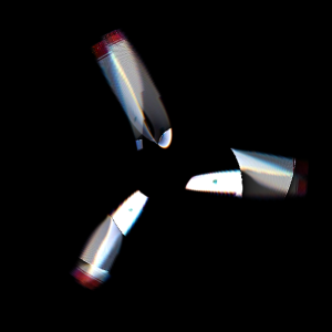
It’s still a bit of a mess unfortunately, but at least looks something like the real object.