How to Make a Digital Polaroid Camera for Cheap Thermal Instant Photos
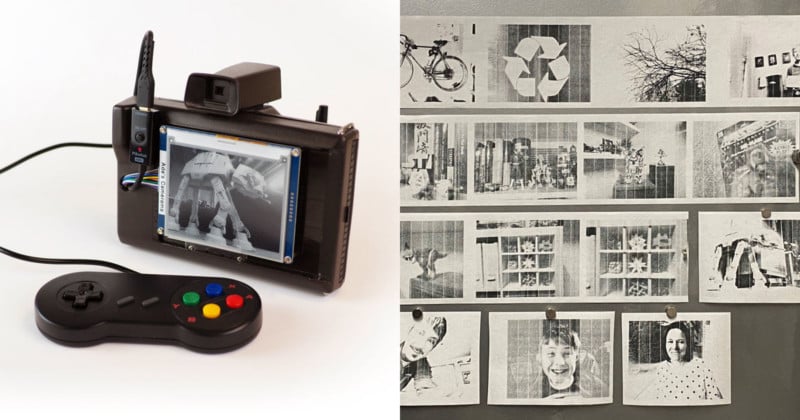
In this article, I’m going to tell you the story of my latest camera creation: a digital Polaroid camera that combines a receipt printer with a Raspberry Pi. To build it I took an old Polaroid Minute Maker camera, stripped out its guts, and replaced the innards with a digital camera, an E Ink display, a receipt printer, and an SNES controller to operate the camera.
There is something magical about a piece of paper instantly coming out of a camera with a picture. It produces a thrill that you just don’t get from the video feeds of modern digital camera screens. Old Polaroid cameras always make me a bit sad because they are such wonderfully engineered machines but when the film went out of production they were reduced to nostalgic artifacts that collect dust on our shelves. What if you could breathe new life into these old cameras by using a receipt printer instead of instant film?
As I am prone to do, this post is going to go pretty deep into the technical details of how I built the camera. I do this because I hope that my experiments inspire a few people to try this project on their own. It’s not a simple modification. In fact, it might be the hardest camera hack I have attempted, but I will try to give enough details from my experience to prevent you from getting stuck if you decide to tackle this project.
Why did I do it? After my coffee stirrer camera made the rounds I wanted to try something a bit different. Looking through my camera collection, the Polaroid Minute Maker camera jumped out at me as a great candidate for digital conversion. This was the perfect project for me because it combined some of the things I was already playing with: the Raspberry Pi, E Ink displays, and receipt printers. Put them together and what do you get? Here’s the story of how my digital Polaroid camera was built…
Introduction
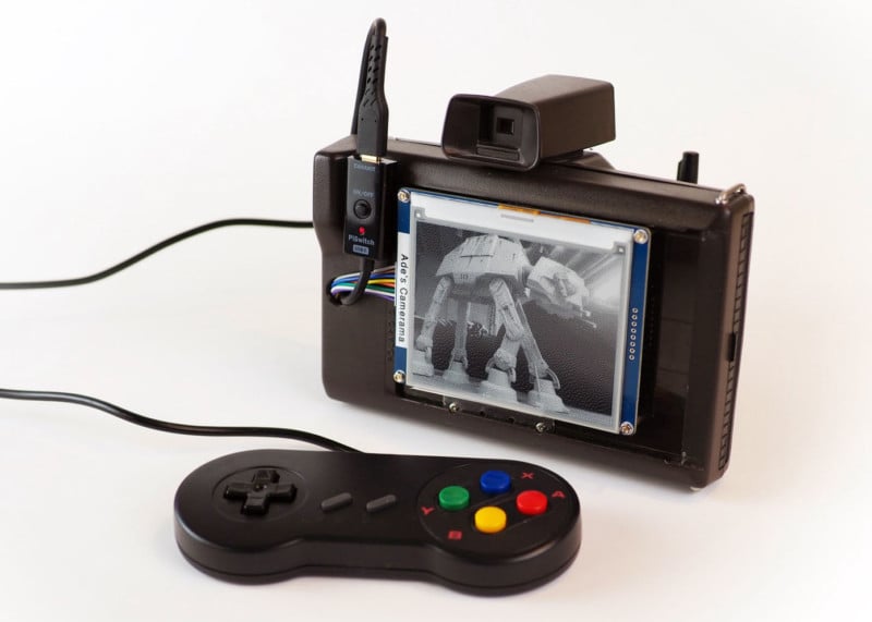
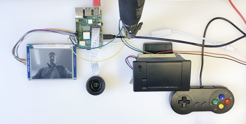
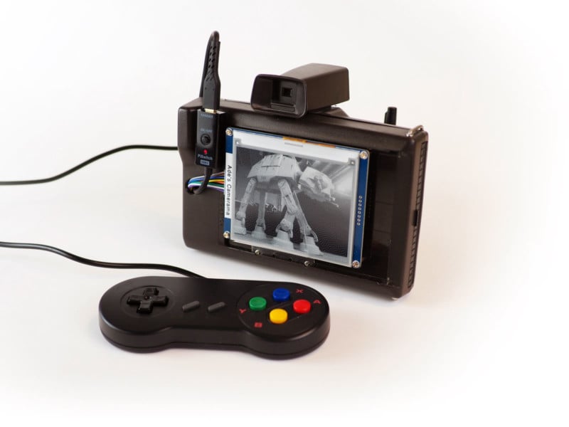
I’ve seen a few people attempt similar projects, but nobody has done a great job of explaining how they did it. I hope to avoid that mistake. The challenge of this project is getting all the various parts to work together. Before you start shoving all the pieces into the Polaroid shell, I recommend spreading everything out as you test and set up all the various components. This will save you from reassembling and deconstructing the camera every time you hit a snag. Below you can see all the parts connected and working prior to everything getting stuffed inside the Polaroid shell.
I made a few videos documenting the process as I went. If you plan on tackling this project you should start with this 32-minute video because you can see how everything comes together and get a sense of the challenges you might face.
Below are the parts and tools I used. When everything is all said and done the cost will probably surpass $200. The big expenses will be the Raspberry Pi ($35-$75), the printer ($50 — $62), the display ($37), and the camera ($25). Part of the fun will be making this project your own, so depending on what you want to include or exclude, upgrade or downgrade, your costs will vary. Here are the parts I used:
Things You’ll Need
Parts
- Polaroid Minute Maker camera (or Swinger)
- Raspberry Pi 4
- Raspberry Pi Camera Module (v2)
- Thermal receipt printer
- Waveshare E Ink display (400x300px)
- SNES controller
- Battery (for printer)
- Battery (for Raspberry Pi)
- USB adapter
- HDMI extension
- Roll of 58mm receipt paper
- Buzzer (optional)
- USB-C extension (to connect to battery)
- USB-C on/off switch (optional)
Tools
- Mouse, keyboard, and monitor (for Raspberry Pi setup)
- Wire stripper/cutter
- Pliers
- Dremel tool
- Soldering iron
- Small screwdrivers
- Hot glue gun
- Wires, super glue, rubber bands, and other random things
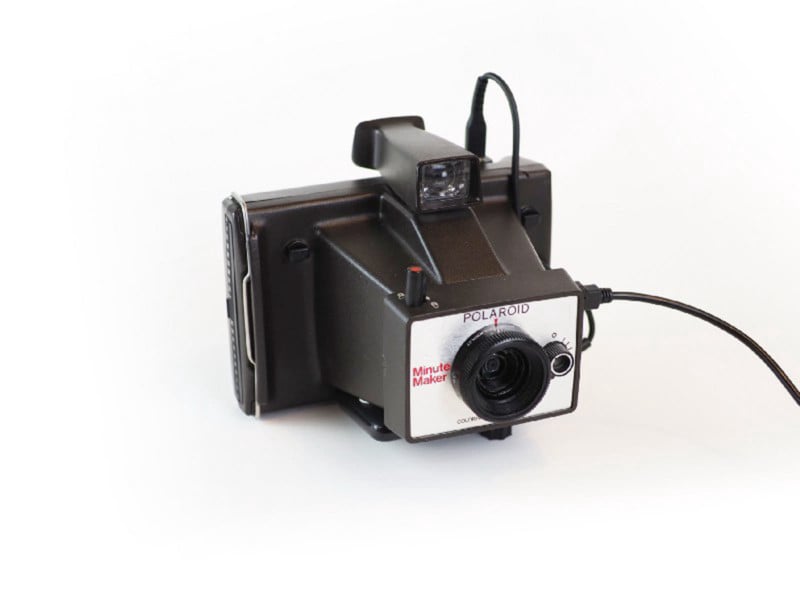
The Polaroid Camera
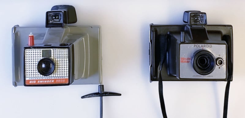
The camera I used is a Polaroid Minute Maker. If I were to do it again I would use a Polaroid Swinger because it is basically the same design but with a prettier front plate. Unlike newer Polaroids, these models have more room inside and they come with a door on the back that lets you open and close the camera which will be very handy for our needs. With a bit of hunting you should be able to track one of these Polaroids down at an antique store or eBay. You can probably snag one for less than $20. Below you can see a Swinger (left) and the Minute Maker (right).
In theory, you could use any Polaroid camera for a project like this. I also have some Land Cameras that have bellows and fold down but the nice thing about the Swinger or Minute Maker is that they are made of hard plastic and don’t have many moving parts other than the back door.
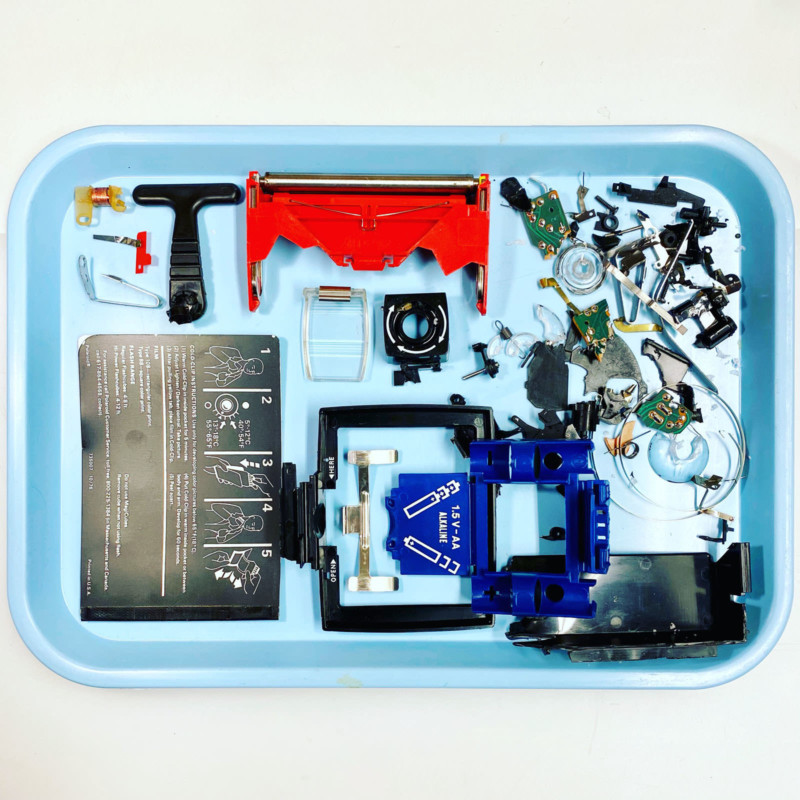
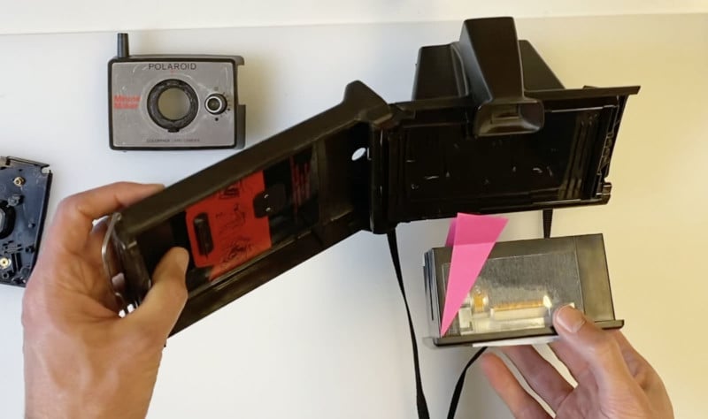
The first step is to strip all the guts out of the camera to make room for all our electronics. Everything must go. By the end you will have a bunch of junk that looks like this:
Most of the parts of the camera can be removed with pliers and brute force. These things aren’t made to be taken apart so you will be fighting against glue in some areas. Removing the front of the Polaroid is harder than it looks. There are screws on the inside that require some tool that apparently only Polaroid has. You might be able to unscrew them with pliers but I gave up and forced the front off. In hindsight, I would take a bit more care here, but the damage I caused was fixable with super glue.
Once you have the front off you are again going to continue battling with parts that aren’t meant to be taken apart. Again, pliers and brute force are required. Just be careful to avoid damaging anything that is visible from the outside.
The lens is one of the trickier elements to remove. There’s no easy solution that I can think of other than to drill a hole through the glass/plastic and pry it out. I wanted to keep as much of the look of the lens as possible so that people might not even see the tiny Raspberry Pi camera at the center of the black ring that formerly held the lens.
In my video, I show a before and after comparison of the Polaroid so you can see exactly everything you will be removing from your camera.
Take care to make sure that the front faceplate can be taken on and off easily. Think of the faceplate as decoration. Most of the time it will be held in place, but should you want to connect the Raspberry Pi to a display and keyboard you can remove the front and plug things in. You can come up with your own solution here, but I decided on a magnet as the mechanism that keeps the faceplate in place. Velcro seemed too flimsy. Screws were overkill. Here’s an animated photo showing the camera with the faceplate on and off:
The Raspberry Pi
I opted for the full Raspberry Pi 4 Model B over the smaller Pi Zero. This is partly for speed, and partly because I am more comfortable working with it since I am relatively new to the Raspberry Pi world. Obviously, the smaller Pi Zero would have some advantages working in the tight space of the Polaroid.
An introduction to the Raspberry Pi is beyond the scope of this tutorial, but there are plenty of resources available if you are new to the Raspberry Pi.
One bit of general advice is to take your time and be patient. If you are coming from a Mac or PC background it will just take some time to familiarize yourself with the nuances of the Pi. You’ll need to get comfortable using the command line and you’ll pick up some Python coding skills. If that scares you (I was intimidated at first too!) don’t be discouraged. As long as you come to it with a mindset of persistence and patience you will get it. Nearly every obstacle you encounter can be overcome with an internet search and persistence.
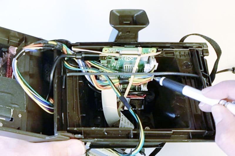
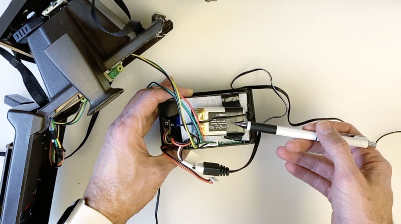
Above is a photo that shows where the Raspberry Pi will fit in the Polaroid camera. You can see where the power connects on the left. Also note the gray divider that extends across the width of the opening. This is basically to create a top edge for the printer to sit against and to keep the Pi separate from the printer. You will want to take care when inserting the printer to not smash the pins that the pencil is pointing at in the photo. The display cable connects to the pins here, and the ends of the wires that come with the display are about a quarter-inch too long. I had to extend the cables with smaller ends so that the printer didn’t press against them.
The Raspberry Pi is positioned so that the side with the USB ports is pointing at the front. This allows the USB controller to connect from the front using an L-shaped adapter. While it wasn’t a part of my original plan, I also ran a small HDMI cable to the front. This allows me to easily pop the front off and plug a monitor and keyboard into the Pi.
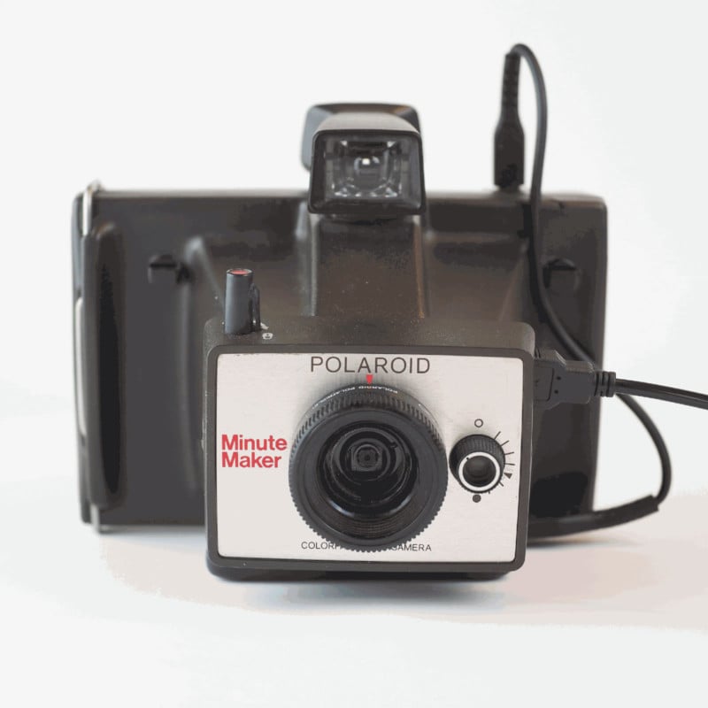
The Digital Camera
The camera is the Raspberry Pi V2 module. The quality isn’t as good as the newer HQ camera but we don’t have the luxury of space. The camera connects to the Raspberry Pi with a ribbon. Cut a thin hole below the lens where the ribbon can fit through. The ribbon will need a twist on the inside before it connects to the Raspberry Pi.
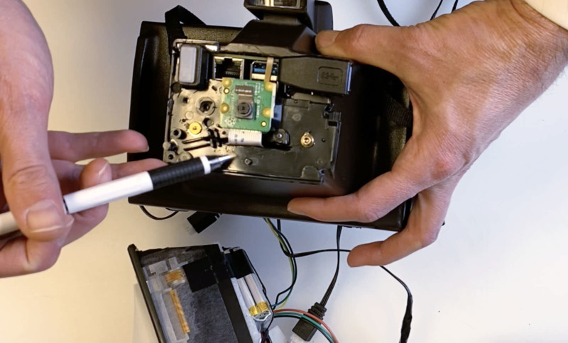
The Polaroid’s front plate has a flat surface that is just right for attaching the camera. To attach it, I used a double-sided adhesive strip. You have to be a bit careful on the back because the camera’s board has some electronic parts that you don’t want to damage. I used some bits of the adhesive tape as spacers to prevent smashing these parts.
A couple of other things to note in the photo above is that you can see how the USB and HDMI ports can be accessed. I used an L-shaped USB adapter to direct the connection to the right. For the HDMI cable in the upper-left corner, I used a 6-inch extension cable with an L-shaped connector on the other end. This can be seen better in my video.
The Display
E Ink seemed like a good choice for the display because the image is so similar to what would get printed on the receipt paper. I used the Waveshare 4.2-inch E Ink Display Module with 400×300 pixels.
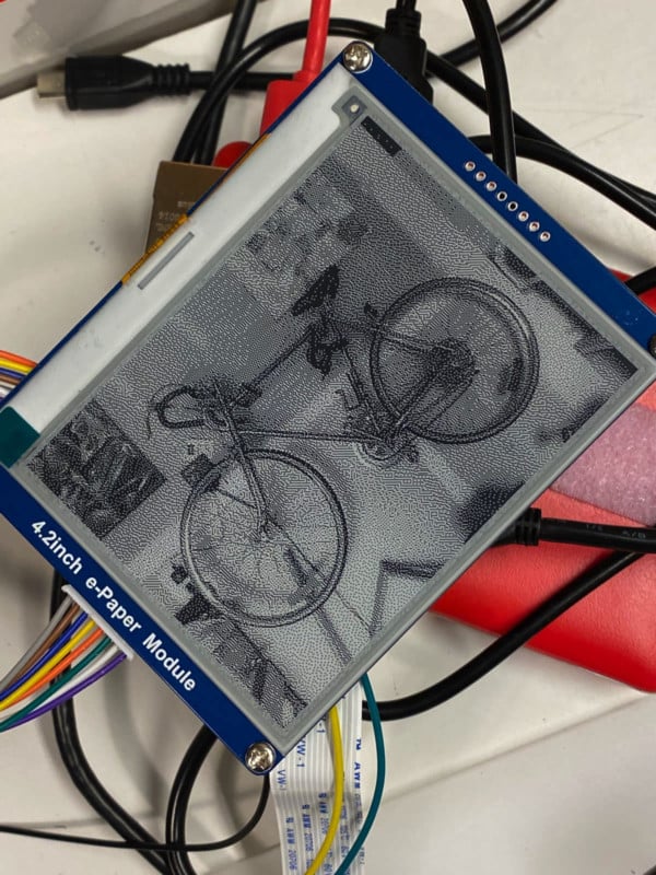
E Ink has an analog quality that I just love. It really does look like paper. There is something really satisfying about having an image on the screen when there is no power. Because there are no lights powering the pixels, once the image is created it stays onscreen. That means that even without power the photos remain on the back of the Polaroid reminding me of what the last photo I took was. And let’s be honest, the camera is going to sit on my shelf much longer than it is in use, so it is kind of nice that the camera almost becomes a picture frame whenever it isn’t in action. The energy savings aren’t trivial, either. Compared to light-based displays that draw power constantly, E Ink only sips energy when it needs to redraw.
E Ink displays have disadvantages, too. The big one is speed. It just takes longer to turn each pixel on or off than a light-based display. The other shortcoming is refreshing the screen. More expensive E Ink displays can do partial refresh, but cheaper models redraw the entire screen every time anything changes. The effect is that the screen goes black, white, then the image appears inverted before the new image appears. The flashes only take a second, but that adds up. All said, this particular screen takes about 3 seconds to update from the time I push a button to the time a photo appears on the screen.
Another thing to keep in mind is that unlike a computer display that shows a desktop and mouse, you need to think of the E Ink display a bit differently. Basically, you are telling the display what to show one pixel at a time. In other words, this isn’t plug-and-play, you need some code to make this happen. Every time a picture is taken, a function is executed that draws the image on the display.
Waveshare provides drivers for their displays but their documentation is terrible. Plan to spend time fighting with your display before things work correctly. Here’s the documentation for the screen I used.
The display has 8 wires that you will be attaching to the pins of your Raspberry Pi. Normally you could just use the wires that come with the display, but since we are going to be working in such a tight space I had to extend the wires with ends that weren’t so tall. This saved about a quarter-inch of space. I suppose another solution would be to cut additional plastic off of the receipt printer.
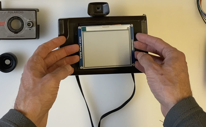
To connect the display to the back of the Polaroid you will drill four holes. The display comes with holes for mounting at the corners. Place the display where you want it, making sure to leave room below for the receipt paper to come out, then mark and drill the four holes. Then screw the screen down from the back. There will be a 1/4 inch gap between the Polaroid’s back and the back of the display.
You might be thinking that the E Ink display is more trouble than it is worth. You might be right. If you are looking for a simpler option you might want to look for a small color display that can connect through the HDMI port. The downside is that you will always be looking at the desktop of the Raspberry Pi operating system, but the advantage is you can just plug it in and go.
The Receipt Printer
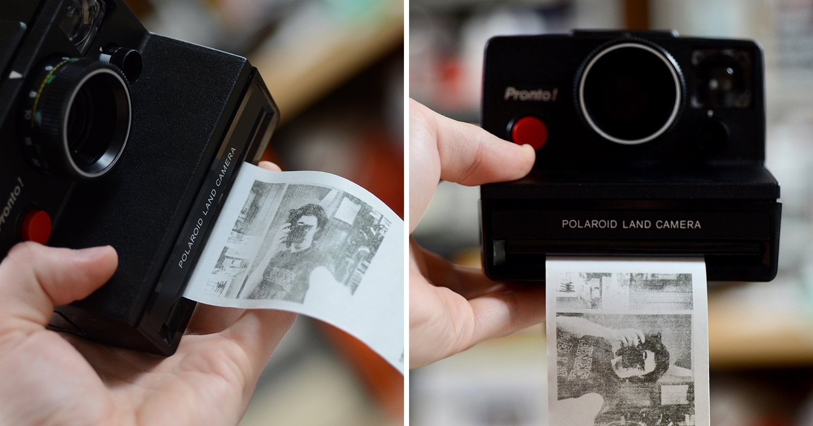
You may need a refresher on how a receipt printer works. They don’t use ink. Instead, these printers use thermal paper. I am not entirely sure how the paper is created, but think of it as drawing with heat. A black area is generated when the heat reaches 270 degrees Fahrenheit. If you were to get the roll of paper hot enough it would turn entirely black. The big benefit here is that no ink is used and compared to real Polaroid film, no complex chemical reactions need to take place.
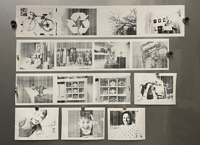
There are cons to using thermal paper as well. Obviously, you only get to work in black and white, there is no color. And even within the range of black and white, there are no shades of gray. You must draw the image entirely with black dots. As you try to coax as much quality out of these dots you will inevitably fall down the rabbit hole of understanding dithering. Of particular note is the Floyd-Steinberg algorithm. I’ll let you go down that rabbit hold on your own.
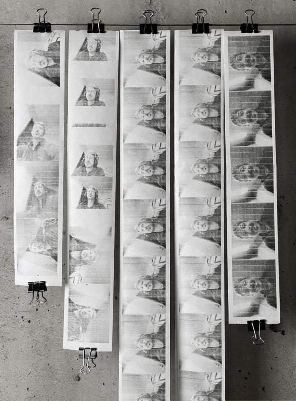
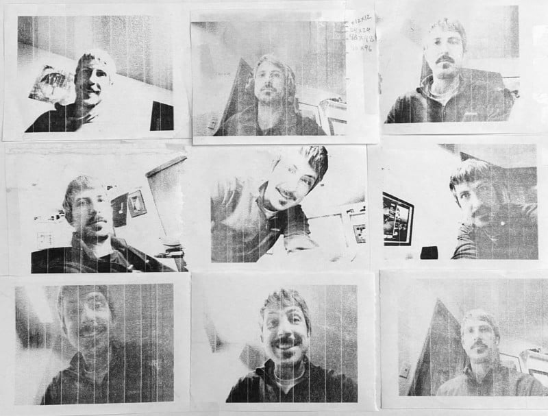
As you experiment with different contrast settings and dithering techniques you will inevitably end up with long strips of photos. Here is a selection of the many selfies that I took as I honed in on the ideal image output.
Personally, I like the look of dithered images. It reminds me of my first art classes when they taught us how to draw by stippling. It is a unique look, but it isn’t the same as the smooth gradations of black and white photography that we have been trained to appreciate. I mention this because this camera is departing from tradition and the unique images it generates should be considered a “feature” of the camera and not a “bug.” If we wanted pristine pictures we can use literally any other consumer camera on the market and save some money in the meantime. The whole point here is to do something unique.
Now that you understand thermal printing, let’s talk about printers. The receipt printer I used was purchased from Adafruit. I bought their “Mini Thermal Receipt Printer Starter Pack” but you could buy the pieces separately if you want. In theory, you could get away with buying a battery, but you probably want the power adapter so you can plug it into the wall while you are testing. The other nice thing is that Adafruit has good tutorials and that will give you confidence that everything will work. Start with this one.
I was hoping the printer would fit in the Polaroid without modification. It’s a bit too big though, so you will either have to cut the camera or trim down the printer. I opted to trim the printer because part of the appeal of this project is to keep as much of the Polaroid’s exterior as possible. Adafruit also sells a receipt printer without the enclosure. This would save some space and a few dollars and now that I know how everything works I would probably use that one the next time I build something like this. That would come with a new challenge of figuring out how to hold the paper roll, however. A project like this is all about compromises and picking the challenges you want to solve. You can see in the photo below the angle that is needed to cut to make the printer fit. This cut will need to happen on the right side as well. Be careful to avoid the wires and internal electronics of the printer when you make the cuts.
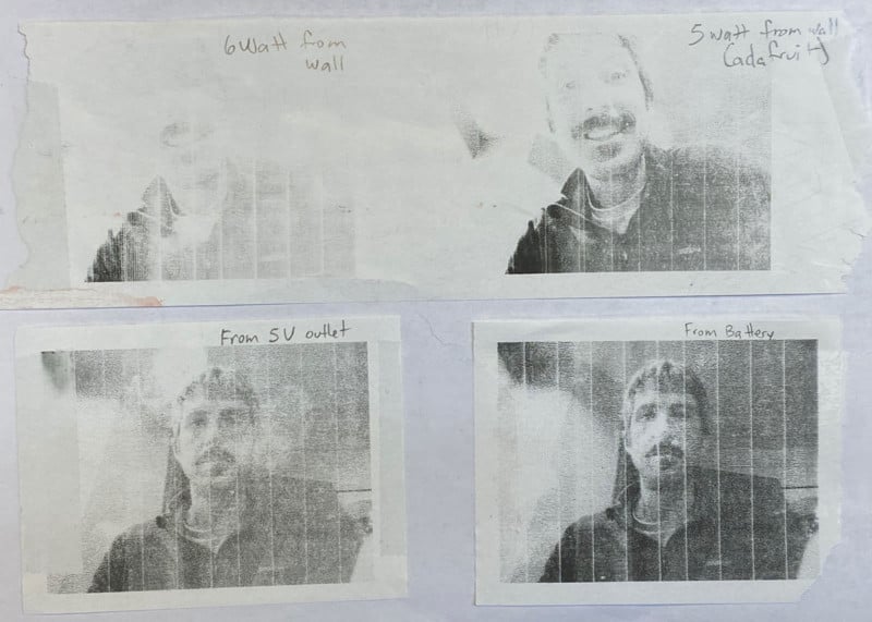
One problem with Adafruit’s printer is that the quality changes based on the power source. They recommend a 5v power source. It works, especially for text-based printing. The problem is that when you are printing images the black areas tend to get light. The power required to heat the entire width of the paper is much more than when you are printing text and as a result, black areas can come out gray. It’s hard to complain, these printers aren’t designed for printing photos after all. The printer just can’t generate enough heat across the entire width of paper at one time. I experimented with some other power cords with different outputs without much success. In the end, I needed this to be powered by battery anyway, so I abandoned the power cord experiments. Surprisingly, the 7.4V 850mAh Li-PO rechargeable battery I chose resulted in the darkest printing of any power source I tested.
Once the printer is fit inside the camera, cut a hole beneath the display that lines up with where the paper will come out of the printer. To cut the receipt paper, I used the blade from an old packing tape cutter.
The other shortcoming aside from the spotty black output is banding. Whenever the printer pauses to catch up with the data it is being fed it leaves a small gap when it starts printing again. In theory, this gap can be avoided if you could eliminate the buffer and let the data stream continuously feed the printer. And indeed, that seems to be an option. The Adafruit website mentions an undocumented pin on the printer that can be used to keep things in sync. I have not tested this because I don’t quite understand how this would work. If you tackle this question, please share your success with me. Here is another batch of selfies where you can clearly see the banding.
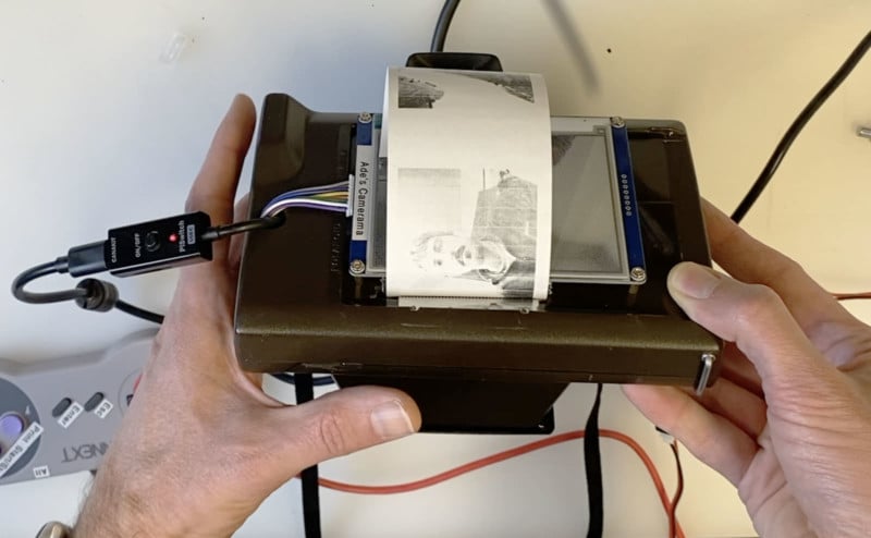
It takes a good 30 seconds to print a photo. Here is a video of the printer in action so you can get a feel for how long it takes to print an image. I believe this could be increased with the Adafruit hack. I have a suspicion that the gaps of time between printing are artificial delays that prevent the printer from out-pacing the data buffer. I say that because I read that the paper advancing has to be synchronized with the printer head. I could be wrong.
Just like the E Ink display, getting the printer working is going to take some patience. There isn’t a print driver, you are essentially sending data straight to the printer using code. Again, the best resource is probably Adafruit’s website. The code in my GitHub repo is adapted from their examples so if you get stuck, Adafruit’s documentation is going to be your best bet.
The SNES Controller
The advantage of the SNES controller, aside from the nostalgic retro benefit is that it gives me a set of controls that I don’t have to overthink. I need my focus to be on getting the camera, printer, and display to all work together, and having a pre-existing controller that I can quickly map my functions to makes things easy. Plus, I already have experience with using controllers from my Coffee Stirrer Camera so it made it easy to hit the ground running.
The retro controller connects with a USB cable. To take a picture I press the A button. To print a picture I press the B button. To delete a picture I press the X button. To clear the display I can press the Y button. I haven’t used the start/select buttons or the left/right buttons on the top, so they remain available for new functionality if I have new ideas in the future.
As for the arrow buttons, the right and left buttons of the keypad cycle through a slideshow of all the images I’ve taken. Pressing up does nothing currently. Pressing down advances the receipt printer paper. This is handy after a picture is printed and I want to spit out a bit more paper before tearing it off. It also is a quick test to know that the printer and the Raspberry Pi are communicating. I press down and when I hear the paper advance I know that the printer’s battery is still charged and it is ready to go.
The Batteries
I use two batteries in the camera. One powers the Raspberry Pi while the other one powers the printer. In theory, you could run both off of the same power source but I don’t think you would get enough power to sufficiently run the printer.
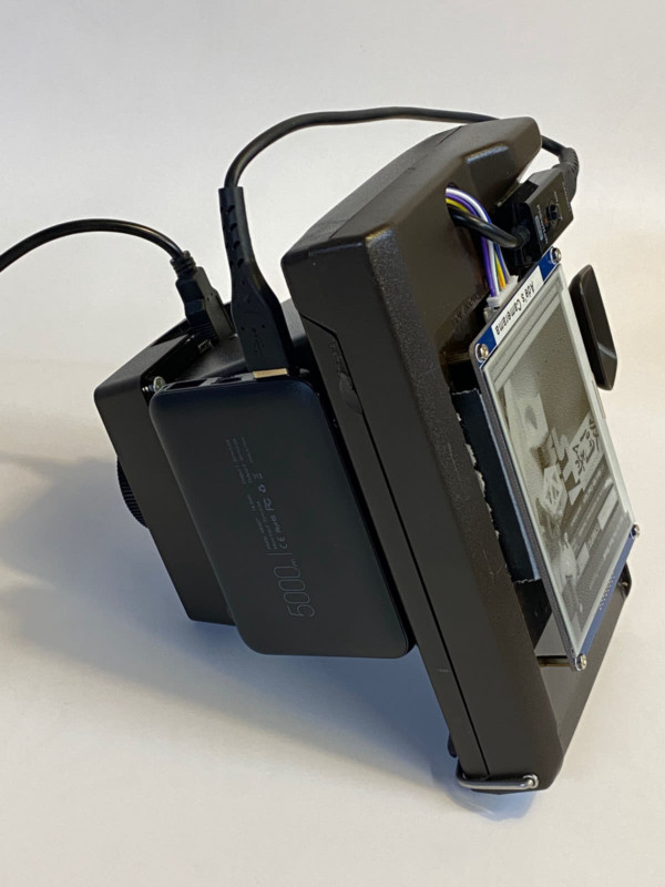
On the Raspberry Pi side, I bought the smallest battery I could find. Sitting on the underside of the Polaroid it’s mostly hidden. I don’t love the fact that the power cord has to run up the front and around to the hole before connecting to the Raspberry Pi. Perhaps you can figure out a way to squeeze another battery in the Polaroid, but there just isn’t much space left. The disadvantage of having the battery inside would be that you would have to open the back to turn things on and off. It’s nice to be able to simply unplug the battery to turn the camera off.
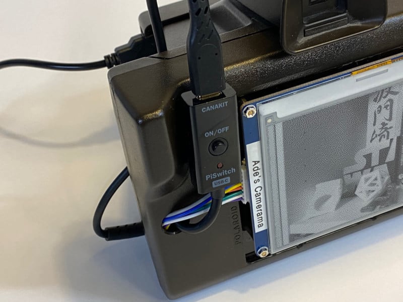
I used a USB cord with an on/off switch that I got from CanaKit. I might be getting a little too cute with this idea. I thought it would be great to just be able to use this button to turn the Raspberry Pi on and off. In practice, it is just as easy to disconnect the USB from the battery.
On the printer side I used a 850mAh Li-PO rechargeable battery. A battery like this has two cords coming out of it. One is the output and the other is the charger. To give me a “quick connect” on the output side, I had to replace the connector with generic 3 wire connectors. This is necessary because I don’t want to have to remove the entire printer every time I need to disconnect the power. A switch would be better here and I might improve this in the future. Even better would be if the switch were on the outside of the camera so I don’t have to open the back door to unplug the printer.
The battery sits behind the printer and I run the wires out so that I can connect and disconnect the power as needed. To recharge the battery, a USB connection is also fed from the battery. I explain this in my video, too, so check that out if you want to understand how this works. As I said, the surprise bonus was that this setup yielded better photo printing than when it was connected directly to the wall.
The Software
Here’s where I need to give a disclaimer. I can write Python that works but I can’t say that it is beautiful. There are surely better ways to do this, and a better programmer could improve my code tremendously. But as I said, it works. So I will share with you my GitHub repository but I can’t really offer support. Hopefully, it is enough to show you what I am doing and you can improve it. Share your improvements with me and I will gladly update my code and give you credit.
Github Repo: https://github.com/adrian3/digital-polaroid-camera
So let’s assume you have the camera, display, and printer all set up and working. Now you can run my Python script which is called “digital-polaroid-camera.py.” Eventually, you will want to set your Raspberry Pi to auto-run this script when it boots, but for now, you can run it from your Python editor or the terminal. Here’s what will happen:
- The most recent photo is sent to the display
- The program watches for button presses on the controller
- When a picture is taken (A button) it is sent to the display
- When the print button is pressed (B button) it prints whatever image is on the display
- The arrow buttons are essentially cycling through a slideshow of all the photos that have been taken
I tried to add comments to my code to explain what is happening, but there are a couple of things happening when a photo is taken that I should explain further. When a photo is taken it is a full-color, full-size image. This image is saved in a folder. This is handy because you will have a normal, high-resolution photo if you ever need to refer to it later. In other words, this camera is still creating normal JPGs like any other digital camera.
When the photo is taken, a second image is created that is optimized for the display and printing. Using ImageMagick, the original photo is resized, converted to black and white, and the Floyd Steinberg dithering is applied. I can pump up the contrast in this step, too, although by default this is turned off.
This new image is actually saved twice. First, it is saved as a black and white jpg so that you can see it and use it again in the future. The second save creates a file with an extension of .py. This isn’t a normal image file, rather it is the code that takes all the pixel info from the image and converts it into data that we can send to the printer. This step is necessary because, as I said in the printer section, there are no print drivers, so you can’t just send a normal image to the printer.
There is also some code to make beeps when buttons are pressed and images are printed. This is optional, but it is nice to get a little bit of audible feedback to let you know that things are working.
One last time, I can’t support this code, it is meant to point you in the right direction. Please use it, modify it, improve it, and make it your own.
Conclusion: What I Would Do Differently
This was a fun project and in hindsight, there are a few things I would do differently or I might update in the future. The first thing is the controller. While the SNES controller does exactly what I wanted to do, it is a clunky solution. The wire gets in the way. It forces you to hold the camera in one hand with the controller in the other. It’s awkward. One solution might be to strip out the buttons from the controller and attach them directly to the camera. If I am going to go to that trouble, however, I might as well ditch the SNES altogether and use more traditional buttons.
Another awkward part of the camera is that I need to open the back every time I turn the camera on or off to disconnect the printer from the battery. It seems like a small thing, but every time I open and close the back I have to re-thread the paper through the opening. It wastes a bit of paper and takes time. I could move the wires and connections to the outside but I don’t want that stuff exposed. The ideal fix would be to have a single on/off switch that controls both the printer and the Pi that is accessible from the outside. Perhaps the printer charger port could be accessed from the front of the camera as well. If you tackle this project consider solving this problem and share with me what you came up with.
The last thing that is ripe for an upgrade is the receipt printer. The printer I used is great for text but it isn’t ideal for photos. I have been on the hunt for the best option for upgrading my thermal receipt printer and I think I have found it. My initial tests show that an 80mm ESC/POS compatible receipt printer is probably going to yield the best results. The challenge is finding one that is small and battery-powered. This is going to be a key part of my next camera project so stay tuned for my advice on thermal printer cameras.
P.S. This has been a long post and I am sure I left out some important details. I’ll come back with updates as I inevitably improve my camera. I really hope you enjoyed this story. Don’t forget to follow me (@ade3) on Instagram so you can keep track of this and my other photography adventures. Stay creative.
About the author: Adrian Hanft is a photography and camera enthusiast, designer, and the author of User Zero: Inside the Tool that is Reshaping Dystopia. The opinions expressed in this article are solely those of the author. You can find more of Hanft’s work and writing on his website, blog, and Instagram. This article was also published here.