How to Make a LIDAR-Driven Motorized Film Carrier
Despite what some people think about LIDAR for cars, in the near future it is foreseeable that this technology will take its rightful place in our daily lives. Not just for cars but with almost anything and everything. We have already seen Apple’s new iPad and iPhone utilizing this technology. I wanted to see if I could use a LIDAR, in its most fundamental function, on a film carrier that is printed on a 3D printer.
Noticing all the cheap LIDAR sensors available on Alibaba and Amazon made me wonder if I could incorporate this technology on this OPEN medium format film carrier. Most common LIDARs make use of infrared frequencies that make them invisible to the naked eye. The LIDAR that was chosen for this film carrier is called VL53L0X. This sensor is designed to measure short distances within the range of a few centimeters to a meter. The module makes use of the 940nm wavelength that is sourced from a Vertical Cavity Surface-Emitting Laser (VCSEL). The light that is bounced back from the subject is detected on an integrated Single Photon Avalanche Diode (SPAD), and from this the time is calculated. The distance is deduced from light’s time of flight (ToF) since distance is proportional to time. The VCSEL used is a Class 1 laser and is safe under all conditions of normal use.
The word LIDAR stands for Light Detection and Ranging. In principle, LIDAR’s are just like RADAR’s; they are directional ranging devices. However, what separates a LIDAR from a RADAR is the electromagnetic (EM) frequency they use. RADAR’s are based on radio frequency (Ra) and LIDAR’s are based on wavelength closer to the visible spectrum (LI). And the remaining abbreviation DAR is Detection and Ranging. Maybe one day these names will merge and become EMDAR.
Important Note: The static electricity created by the film carrier is channeled to the LIDAR via the mounting screw. This causes the LIDAR to freeze, and a restart is required. To avoid this do not use the screw to mount the LIDAR.
Designing with FreeCAD for 3D printing
It was the first time I was using a 3D printer. Bizarrely, everything went super smooth with the first test prints. However, it was time to design a film carrier, and the last time I made any technical drawing was many many years ago. Moreover, I was only taught to make a technical drawing on paper using a T-ruler and a compass. But because 3D printers did not understand paper-based technical drawings, I needed to learn how to use computer-aided drawing (CAD) software.
Because Fusion 360 (by AUTODESK) was in process of changing its free license terms, and SOLIDWORKS can be afforded by companies usually. This left me with using FreeCAD! I soon found out how much FreeCAD was packed with features. Maybe, even too many; this open software was developed by hundreds and hundreds of developers over the past 18 years. It felt a bit like a jungle at first. I found out that there were correct ways of designing, and there were really correct ways of using FreeCAD. One that makes going back and refining designs easier.
With that said, it did not take very long before I stumble upon the notorious “Topological Naming Problem” of FreeCAD. This issue arises when you decide to change a previous feature of your design, which ends up breaking a reference that is used downstream due to the change in the number of faces and edges. This and other smaller software bugs almost made me give up on FreeCAD. But I decided to press on and make it work for me. And did it work!
Some of the YouTubers who also made my learning process easier were: Brodie Fairhall, Jayanam, flowwies corner EN, Martham Engineering, MangoJelly Solutions, Andrew CAD, and Joko Engineeringhelp. So a big thanks goes to them!. That said, I am continually learning how to use FreeCad in better ways and more efficiently. To conclude, FreeCAD is like any other analog camera; it may have its limitations, but the more you use it the faster and more efficient you become on it. And due to its active developers, I can only image it will improve even further. The FreeCAD that is currently under development is also rumoured to have tackled the notorious “Topological Naming Problem.”
Printing with a 3D printer
After designing a part on CAD software and generating its solid digital mesh, an .STL file, I needed to figure out how to print on a 3D printer. I soon figured out that 3D printers needed G-codes that were generated from slicer software. To my surprise I realized how separated CAD software and slicers were; one naturally assumes these two designing tools could benefit if they were a bit more merged.
A G-code contains information such as a cross-section of your design layer by layer, the temperature used to melt the filament, the temperature of the bed, fan speed for the solidifying plastic part, etc… In order to create a G-code I came across two software: PrusaSlicer and Cura. I had to choose one, and I randomly settled on PrusaSlicer. In hindsight, maybe it was because I could not afford a Prusa 3D printer or an e-3D printer.
I needed to find out typical settings that would work on my 3D printer. I ended up finding a YouTube video that had just that: prusaSlicer setting for Ender 3 (BV3D Bryan Vines). This setting worked so well that it ended up hindering my learning process. Troubleshooting some of the problems I had sometimes took a long time as there were a lot of setting I did not fully understand. However, there is a rich 3D printing community online, which makes learning very easy and fun. Some of the YouTube Channels that immensely helped me improve my understanding of 3D printing were: CNC Kitchen, Teaching Tech, and CHEP.
Creality Ender 3 v2
Perhaps it is because it’s my first 3D printer, but I really love this printer. Out of the box, this printer was optimized to print polylactic acid (PLA). PLA is great to print with because it melts and flows very nicely, it does not absorb water from the air as much, and it is not as sensitive to fluctuating room temperature during printing. Its biggest drawback is its glassy state (warping) that begins around 65 degrees Celsius.
The Ender 3 printer has a Bowden extruder, which means that the filament is pushed into the printing nozzle from a distance away via a Bowden tube. Unfortunately, the pneumatic couplers used on the Bowden tube will eventually fail. The good news is that replacements for a better part are only a few dollars and are fitted very easily. In fact, upgrading 4 things, which will cost under 30$ US, will take this printer to another level. These are: changing the plastic extruder for a metal one, using stiffer leveling bed springs, using Capricorn PTFE tubing, and pneumatic couples (see items section). Perhaps this was what initially made Creality Ender 3 to become the most modified 3D printer in the world.
The printer’s stock hotend prints PLA very nice and is very reliable. However, one of its drawbacks is that the PTFT tube is within the hotend that can go up to 200°C-220°C during PLA printing. Unfortunately, the PTFT tube has a Teflon lining that starts to disintegrate just above 220 degrees, creating poisonous vapors. The same happens when you sear red meat on a Teflon pan as well. Therefore, I decided to play it safe and decided to purchase a Micro-Swiss’s all-metal hotend (see items section) that separates the Bowden tube from the hotend with a titanium heat stop.
Maybe today’s single nozzle filament 3D printers are not as fast as some might like them to be. However, to design something unique and transform a virtual design into a physical object on that very day is super fun. This makes me wonder why I didn’t own a 3D printer earlier. I believe in the near future we will see double/triple or quadruple nozzles working simultaneously on the same part, as I believe this is only a software challenge at this point. Some nozzles are already printing at speeds of 140 mm/s. However, most people today will cut time by owning multiple 3D printers. One well known 3D printing farm is owned by the company Prusa. This farm has more than 400 3D printers that constantly print new parts for its new 3D printers.
In addition, companies such as Voltera are also now demonstrating PCB printing for electrical circuits. I imagine, not too far in the future, printing physical parts and electronics will merge. If components that are used are constantly fed in a production line, I don’t see why 3D printers can not be self-sufficient to produce a complete 3D printer. Just like self-replication.
OK, back to printing and assembling a film carrier!
The Outline
- Main design goals
- Main features of the film carrier
- 3D printing the parts
- Assembling the film carrier (link for downloading the Film Carrier)
- The electronics to the film carrier (link for downloading the Arduino Sketch)
- Future directions
- Items used and cost
There are lots to cover. So let’s begin!
1. Main Design Goals
Use front rollers to intake film and rear rollers to push film out from the film carrier.
Utilize the LIDAR to automate the film intake.
Utilize the LIDAR to determine whether the is film precut (short) or newly developed (uncut and long).
Flatten the film in the film carrier for sharp scanning by applying longitudinal tension and lateral stiffening that arises from precise film bending.
Toggle between different film formats (645, 6×6, 6×7, 6,9, and 135) for precise stepper motor progression.
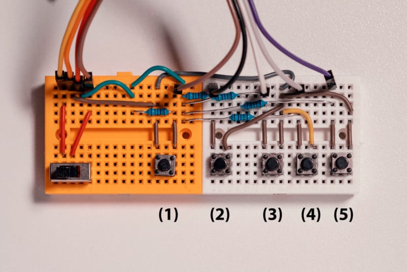
Use micro-steps (button 3 and 4) to perfectly align the film under the camera.
Make the process of revisiting archives easy. Archived films are usually cut and sleeved. Thus, the adjustments made with the micro-steps, before any picture is taken (before button 2 is used), is temporarily stored in the system with the assumption that the remaining film strips will be pushed to the same location (under the lens).
Use magnets and brass inserts for a sturdy film carrier construction, and a rubber bottom for a good grip.
2. Main Features of the Film Carrier
When the film carrier is switch on, the system will automatically commence with a LIDAR calibration to determine the surface height. If the optional RGB LED is utilized, it will indicate the completion of this calibration by turning RED. Because color film is more transparent to 940nm frequency, compared to a black and white film, a quick calibration on the films are needed. This automatically is executed everything the first film is inserted. This difference in these measurements allows the system to understand if a film is inserted or not without the film being touched.
The film enters into the film holder with a specific sequence that ensures correct film bending. After the film enters the carrier it backs out a bit and then moves to its final position. At this point, if the user uses button 3 and 4, for moving the film in micro-steps, the system will assume you are aligning the picture frame under your camera lens. This new location is automatically recorded and used on the next film strip. This feature is active every time a new film is inserted. This is especially helpful when unarchiving sleeved films.
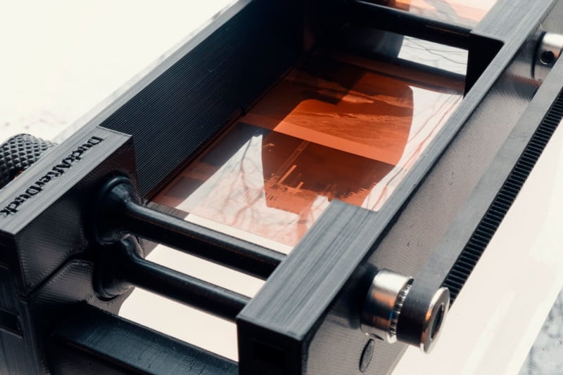
Most of the effort was focused on reliably keeping the film flat within the film carrier. The major difficulty arises from the fact that medium format films do not have a lot of emulsion free edges compared to the total film width. In addition, the nature of thin films, differences in film stiffness and different levels of film curls all contribute to making this task even harder. I had more than 15 design iterations. I also began to review academic papers to understand the physics of bending thin films, but before I drew any meaningful results, my last film carrier iteration luckily worked very well. That said, this design did not perform very well with films that had a heavy longitudinal curl (due to the emulsion). The next design I made had the best all-around performance, but this required a specific film entry sequence to ensure correct film bending, as mentioned in the paragraph above.
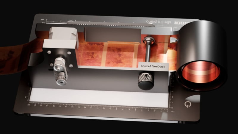
With bending film, it is desirable to work with gravity. Having the film bend longitudinally in a U shape, with emulsion facing downwards ensures the film edges exert pressure on the guiding rails (red line in the figure below), without opposing gravity. However, it is crucial that this pressure is not too great either. Otherwise, it will begin to bend laterally due to the nature of the thin film. The interesting part was to strike a balance between sufficient bending of the film, so that the film longitudinally complies, but not too much so that the lateral bend does not warp the film surface. In hindsight, I think I would have benefited from learning how to apply a finite difference simulation on this problem.
The partial solution to this problem was achieved with the design below. The red track shows the location and the amount of film bending applied by tracks. To show this, the rendered image below sets the main body out of the way.
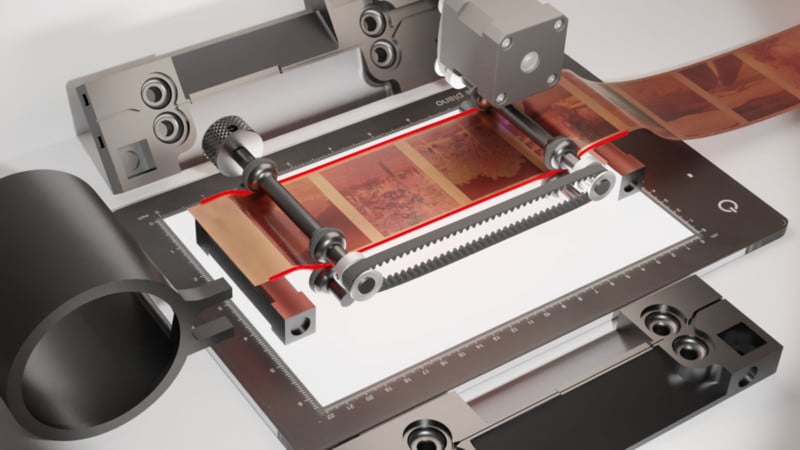
Furthermore, for uncut films, like in the figure above, the rear push out rollers (left side) has another function. The diameter of these rollers is slightly larger than the intake rollers. Hence, when they make equal turns, the amount of distance covered by these rollers are slightly larger. This ensures a little tension on the film that further keeps the film flat on its tracks. Therefore, whilst assembling the rollers, make sure circle labeled rollers are used for the rear push out position, and minus labeled rollers for the front intake position.
3. 3D Printing the Parts
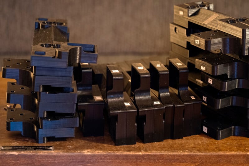
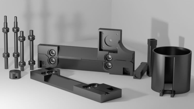
In total there are 10 parts to be printed, with one being an optional part. Two make up the main body, 2 spacers that ensure a specific length between the main bodies, 4 rollers (2 for the film intake and 2 for the push out), and lastly, the tactile round handle. The optional round collector part is for anyone who has their uncut film wander off to a mysterious location on a desk after a scan.
Some typical 3D printing settings I have used are the following. For the main body, I generally use at least 2 solid bottom layers and 5 top solid layers, 2 perimeter lines, with 20% infill (10% is also fine). The z-axis resolution was set to 0.25 mm, using 50 mm/s extrusion rate for the perimeters and 70 mm/s for the infill. The two main bodies can take around 12 to 15 hours of print time. For the rollers, I would suggest higher than 40%, possibly even 100% infill.
I have used polylactic acid (PLA) to print these parts. The heat generated by the stepper motor is not enough to warp the prints. However, if you are constantly using the stepper motor for an hour or two, this will soften parts that are in contact with the motor. Therefore I have added a code that will switch off the stepper motor after 15 seconds of inactivity, and there is a switch to turn off the stepper. In the future, I will probably print in Nylon or carbon fiber filled Nylon to combat this warping.
The figure below shows some of the printing orientations for the parts. The printing should be relatively easy even for an inexperienced person (such as me). The main body only needs a tiny support for the section for the part that hides the 4 screw heads. The rollers benefit from a support shown below (right side) in green. I noticed that the nozzle sometimes tipped the print over without it. The spacers and the film collector are also oriented vertically, similar to the rollers.

4. Assembling the Film Carrier
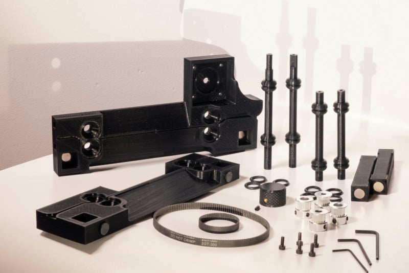
After printing the parts needed it is a good idea to gather all the pasts needed for the assembly as seen in the figure below. These are everything needed, except for the electronics used. This will be covered in the next section.
There are 2 timing belts that are used (Item 1). The shorter timing belt (110mm) transfers the torque from the stepper motor to the intake roller. The longer timing belt, 300mm, transfers the torque from the intake roller to the push-out roller. There are four 20-teeth pulleys that are used in this process. The handle is located on the push-out roller, and the design has a pocket where it allows a brass thread to be melted in, as an insert, using a soldering iron (Item 2). A grub screw is then inserted in this thread so that the handle is firmly attached to the roller. Round magnets are attached to the main body at 4 different sights as well as on the 2 spacers, as shown in the figure below. The plumbing gasket seals roll into their place on the roller, which applies a grip on the film edges.
I would imagine that these printed parts either will fit perfectly, and in this case, there is no reason to use the magnets and the brass thread, or a tad loose. If they are slightly loose, there are pockets within the carrier body and spacers. Sometimes the magnets did not need any adhesive as it required a bit of force to place them in. However, if needed, an ordinary superglue worked well (hot glue was not strong enough).
The assembly process should be simple. If the parts are a bit snug it can also loosen over a day or two as they will adjust to each other. You can DOWNLOAD The source files or the .STL files from HERE.
For clearer assembly instructions, do not forget to check out the video above.
5. The Electronics for the Film Carrier
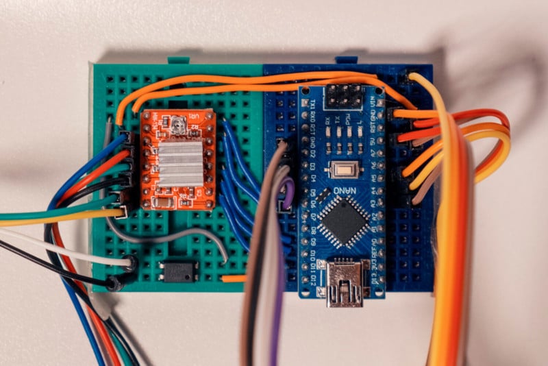
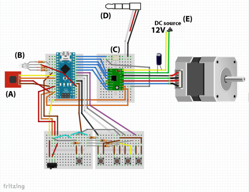
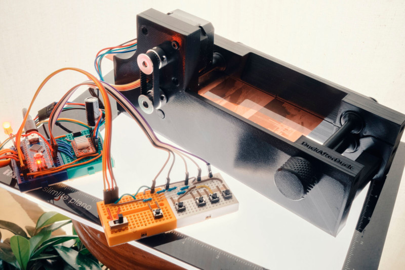
After assembling the electronics you can DOWNLOAD the Arduino Sketch from HERE for uploading it to your Arduino Nano.
6. Future Directions
Even though encoders would make more sense for this application, using them would also result in more rollers and more contact with the film. Maybe more robust sensors around IR frequency would make good alternatives to the current setup.
Source files for this film carrier are available on my GitHub I would be very interesting if anyone implemented other features to this film carrier. Perhaps track designs that keep the film even flatter, etc. Spacer designs for 135 format film, or super 8.
I did not see an awful lot of use for fully automating this film carrier for medium format as 16 images are the most one scans on an entire role. But merging the fully automated film scanning python program, from my previous blog post, could be interesting for some people.
In the near future, I will probably print this film holder using carbon fiber nylon filament for better rigidity, and better temperature resilience.
Controller boards such as ESP32 that is WiFi-enabled or Arduino Nano 33 BLE that is Bluetooth capable can be used to turn a cell phone into a controller for the film carrier too.
I really enjoy looking at the microcontrollers, capacitors, and a colorful breadboard, so I do not plan to make an enclosure anytime soon. But it would be interesting to see cool enclosure designs for this open film carrier.
7. Items used and costs
I generally used Amazon to purchase what I needed for this project. This was mostly out of convenience. It also didn’t require me to physically go to shops during the pandemic. Sometimes I also bought more parts than I needed, thinking I might want to use them for other projects. If you also end up with parts you do not need at the end you can always donate them to your local schools. However, depending on the quantity and the place you order the parts from, for the film carrier, it can cost you as low as 100 US dollars. If you include the 3D printer it would cost around $400 dollars (without upgrades).
I have linked items below to mostly make it easier for finding the right parts. But if you use the links below for your purchase I may receive a small commission. This possible kickback could also motivate me to share other projects in the future. Using these links does not affect the price. That said, I also suggest you use other websites for better prices.
Below are the items I have ordered and used. Some have * attached with them. This is because they were no longer available, but should work the same way.
3D Printer
- Creality Ender 3 v2
- Micro-swiss hotend
- Upgrade Ender 3 (Capricorn Bowden PTFE Tubing, Metal Extruder, Teflon Tube Cutter, Stiffer Spring, Pneumatic coupler)
Film Carrier
- 110mm and 300mm closed Loop Rubber Belt
- Brass thread insert
- GT2 20Teeth 8mm Timing Pulley
- GT2 20Teeth 6.35mm Timing Pulley
- GT2 20Teeth 5mm Timing Pulley
- Hex screw and bolt set, for m3 6mm
- O-Ring Assortment, for size 11×2.5
- Cylindrical bumper pads, size: 10mm x 3.5 mm
- Hex grub screw set for M3x8mm
- Round disc magnet, size: 10mmx2mm . I only found 10mm by 1mm *
Electronics
- Arduino Nano
- Stepper motor controller A4988
- Optocoupler ,
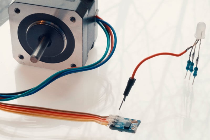
- LIDAR ToF sensor
- Nema 17 stopper motor
- Push buttons
- Switch
- Capacitor ,
- 4 pin RGB LED and resistors (430Ohm and 470Ohm also works)*,
- Jumper Wires and preformed jumper wires
- Mini bread board
I hope you have enjoyed this how-to manual. If you have any questions or suggestions please don’t hold back.
About the author: Seckin Sinan Isik is a photographer and programmer who likes practical aspects of programming to tackle real world problems. The opinions expressed in this article are solely those of the author. Isik enjoys experimenting with photography as much as prototyping and developing new designs. Graduated from Physics, he holds a master’s degree both in Optical Engineering and Molecular Biology. You can find more of Isik’s work on his website, Facebook, and Instagram. This article was also published on his blog.