How to Shoot Rollout Slit-Scan Photos with an Ordinary DSLR
“Slit-scan photography,” as it’s known these days, has a long history. It is related to focal plane shutter distortion in the film era and to the rolling shutter effect in the digital age.
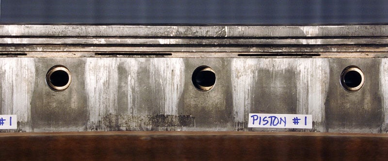
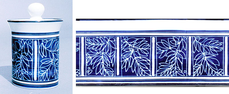
What are rollout photographs? They are single photographs that show the front, sides and back of a subject — typically pottery and archaeological objects, fingerprints on round surfaces, wear pattern of pistons and tires, etc.
These 360-degree rollout photos can be made in many ways. One could use a “slit-scan” app for smartphones, or simply roll a cylindrical subject on the glass surface of a flat bed scanner along with the moving light “wand”. Or, at the real high end, one can use a linear array such as built into a (super expensive) Better Light scanning back for large format cameras.
There are other “systems” as well, such as taking a whole bunch of photos of a rotating subject and taking out only a few lines out of each frame and then adding them up sequentially — this mimics the behavior of a linear array.
But… a persistent question that I have been asked is: Can I make rollout slit-scan photographs in-camera with my basic DSLR camera? And if so, how?
The answer is yes, and in this post I will show you how.
To begin with, in the digital realm, a slit-scan system at its fundamental level deals with only a single line of pixels. A linear array of pixels instead of a 2 dimensional array as in camera sensors. Thus a scanning system such as based on a linear array implies that one will be looking at only a narrow segment of a scene at a time.
In the “real world” one can essentially duplicate the behavior of a linear array by looking at a subject through a narrow vertical aperture or slit. In our case our subject, as we attempt to make a 360-degree record of the surface features of a subject, it will be placed on a rotating turntable or rotating pedestal.
But regular cameras capture all of a scene all at once. How do we make the camera record what happens behind the slit over time? We can accomplish this by panning the camera during a long exposure. The panning action causes the image of the slit to traverse the viewfinder and this takes place over time, meaning one side of the frame will be exposed at a different time than the other. This is the principle underlying slit-scan photography.
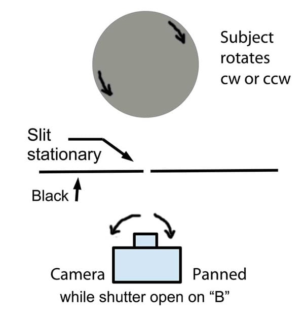
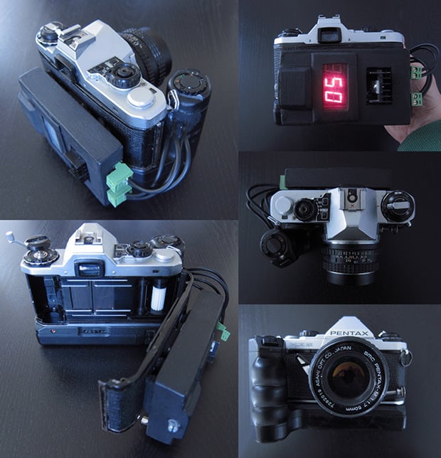
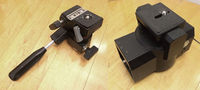
The first step for making a rollout photograph is to place the camera on a tripod pan head and then set-up a situation where the screen in front of the camera is as dark as we can make it… except for a narrow slit or vertical aperture. The camera, attached to the panning head, and positioned so that when the camera looks straight ahead the image of the slit falls in the middle of the viewfinder. The panning head can be one removed from a video tripod or a motorized one.
The first thing to do is to aim the camera towards one side of the screen so that the image of the slit is outside the viewfinder. Then, after opening the shutter, the camera is panned to the other side while the subject, on a turntable or rotating stool, makes one or more rotations. The changing features of the subject, as it rotates in front of the slit, are recorded sequentially, slit-scan fashion, across the camera’s sensor and you make a periphotograph or rollout photograph.
That is the basic idea. To improve on the system here are a couple of suggestions that should improve at least the technical quality of your photographs.
Uneven rotation of the camera will cause vertical “bands” to appear in the finished product. Unevenness in rotation rate causes local exposure time changes which result in changes in exposure. To achieve steadier rotation of the camera, you could use a motorized camera mount instead of doing it by hand.
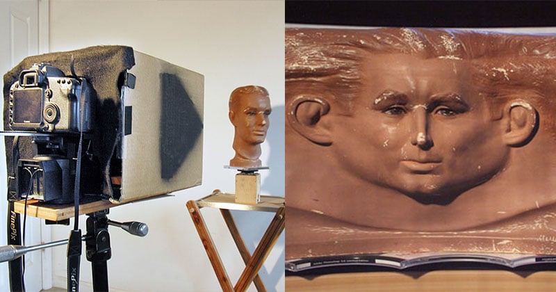
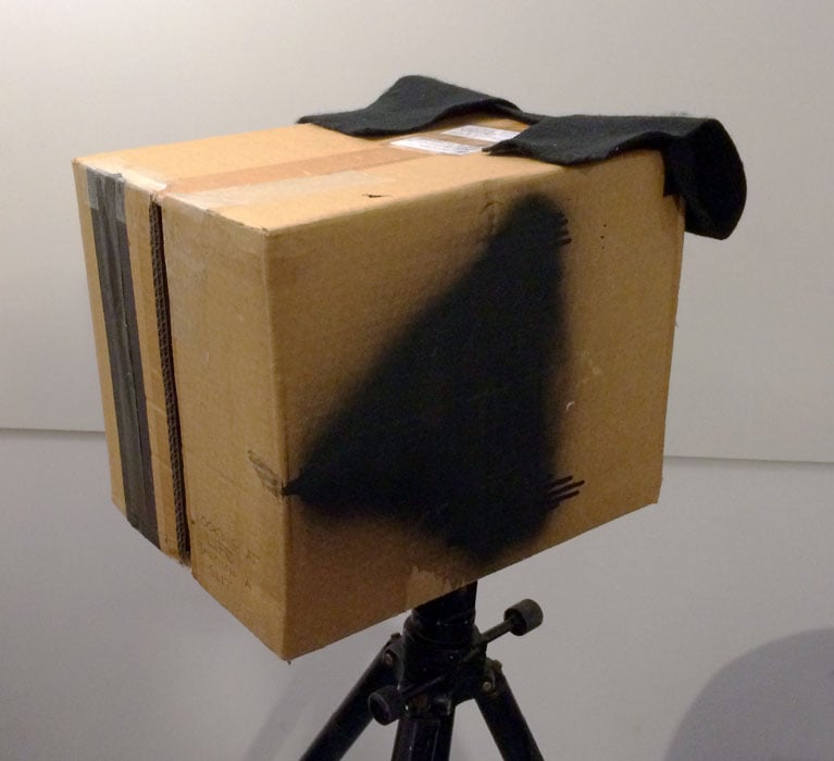
Going further, instead of a screen in front of the camera one can place the camera at one end of a blackened box so that the camera “looks” into the box with the slit located in the opposite side of the box and facing the subject.

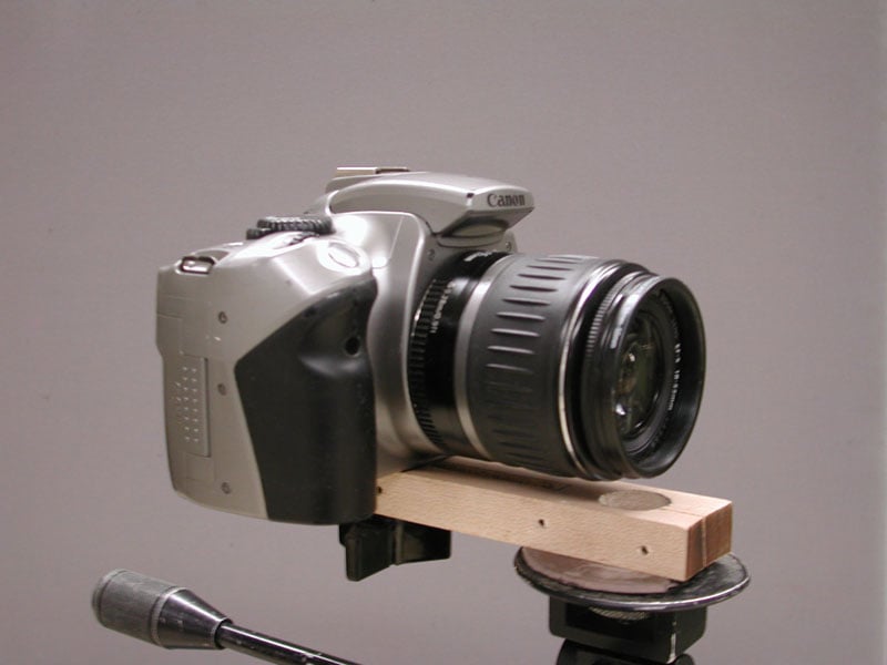
For best results the camera should be rotated about the center of perspective or nodal point of the lens and not about the camera’s tripod socket. To accomplish this you attach the camera to what I call a parallax bar and is similar to the device used for scanning panoramic photography. Then you attach the bar to the pan head.
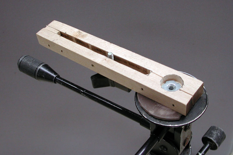
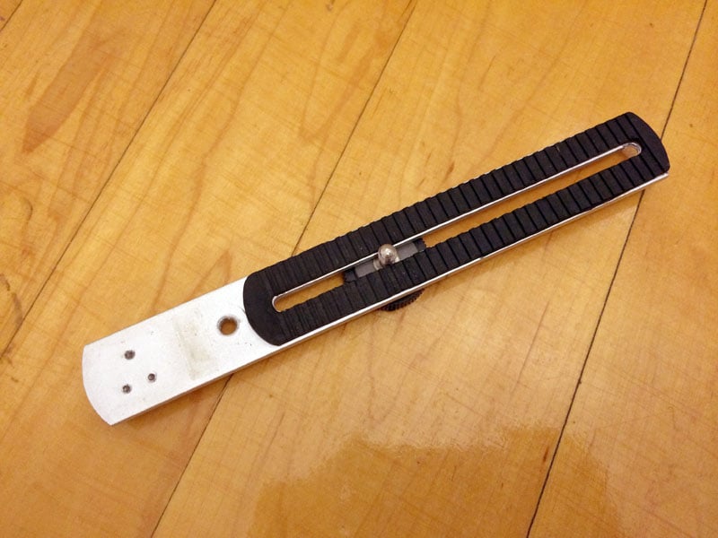
One can make a parallax bar from scratch to accomplish this or one can use a readily found bracket such as used to place a flash unit to the side of a camera. These usually have a tripod socket built-in and a slot with a bolt that fixes the camera to the bracket. The bracket’s tripod socket is affixed to the panning head or the motorized camera rotator and the camera is affixed to the bracket with the threaded bolt in the slot of the bracket.
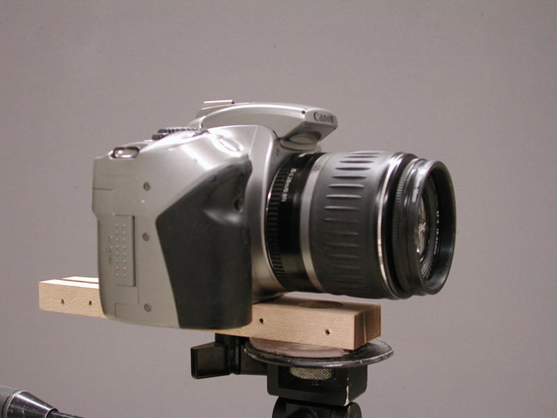
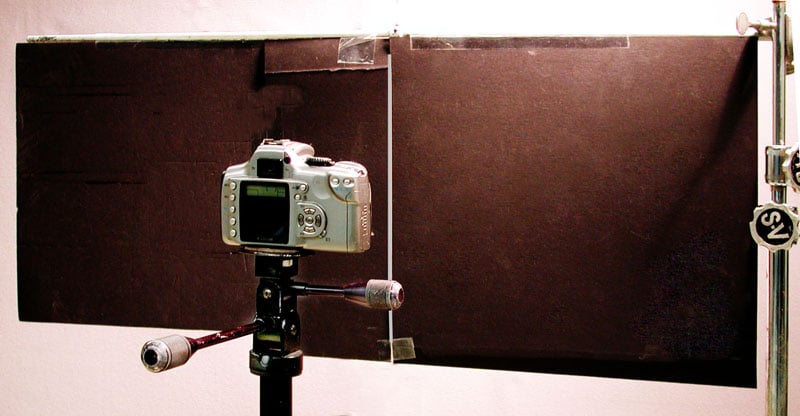
By adjusting position of the camera along this bracket (parallax bar) you want to establish a situation where an object seen through the slit when the camera is aimed towards the right, for example, remains visible through the slit all the time until the slit reaches the left side of the frame. This is shown in the illustration below, in which a pencil was located a couple feet away from the slit in front of the box.
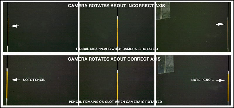
You can see that in the top case the pencil is only visible on the slit when the slit is centered in the viewfinder. When the camera is panned left or right the pencil disappears. On the other hand, when the camera rotates about a point typically somewhere below the middle of the lens the pencil is seen through the slit whether the camera is aimed to the left, center, or right.
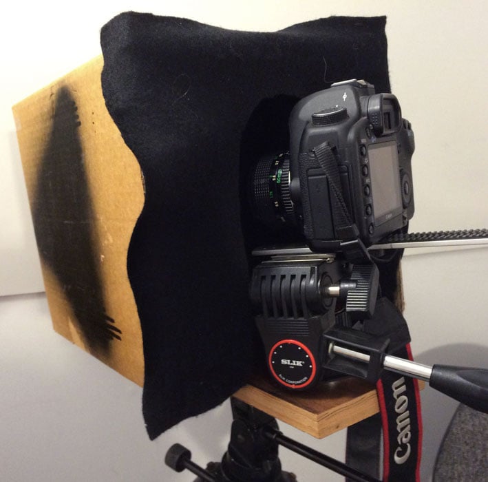
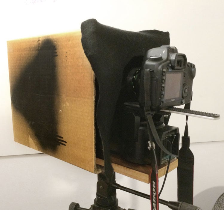
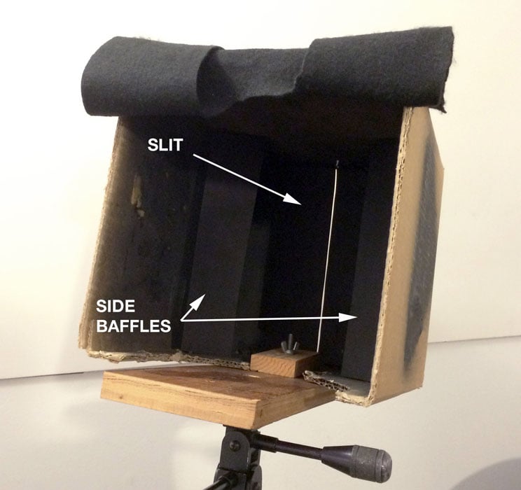
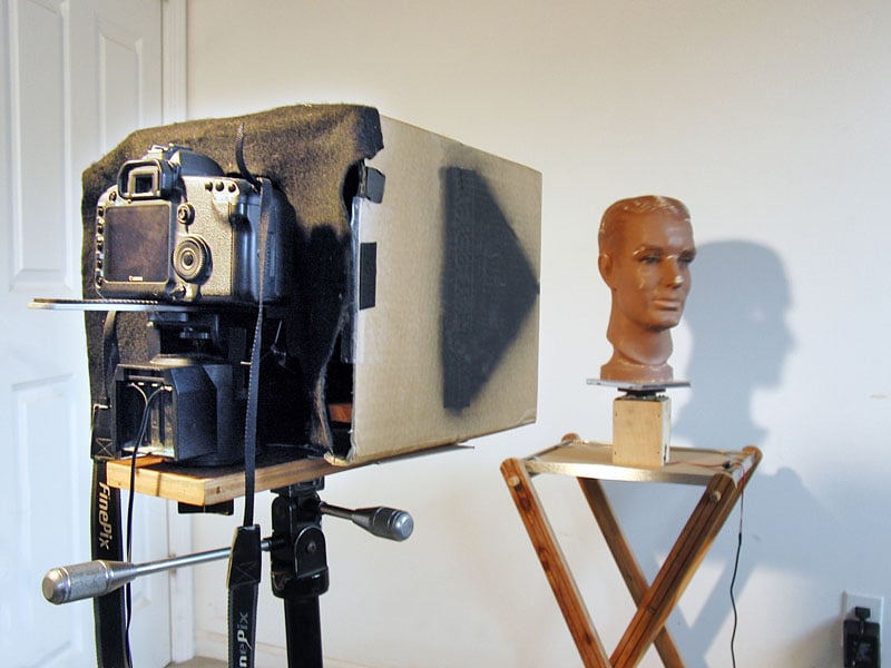
This is the appearance of the box with the camera attached to the parallax bar which in turn is attached to a video tripod head or a mechanized camera rotation platform. These are in turn attached to a base which serves to hold the box and the camera in alignment. Note the black felt baffles at the back of the box. These are loosely fitting baffles whose purpose is to reduce the amount if light reaching the inside of the box. The darker you can keep the inside of the box the better. Note that inside the box there are stiff, blackened, baffles on either side of the box. These are designed to diminish the effect of light reaching the inside walls of the box from light coming into it though the slit.
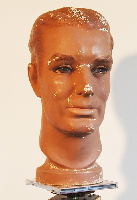
To simplify matters we proceed with the making of a rollout portrait using a mannequin head as the subject. It is placed on a turntable. It is best if the turntable has variable speeds. The camera in this case is attached to a motorized rotating pan head but that could be replaced by a manually turned head as explained earlier.
To get started now we align the camera with the pan head so that the image of the slit (and whatever is in front of it) is located at one side of the camera’s viewfinder, out of the field of view. The viewfinder should be totally black. Then, keeping the shutter of the camera open, we pan the camera so the image of the slit moves across the frame and thus across the sensor of the camera.
It is best if the camera is panned in the same direction that the subject’s surface is moving. Then, as it moves, the slit and the image of whatever lies beyond the slit are automatically and sequentially recorded by the camera’s sensor. Once the image of the slit reaches the other side of the viewfinder the shutter of the camera is closed.
Note that you will be using either a long shutter speed (a shutter speed a bit longer than it takes to pan the camera) or use “B” to start and stop the exposure. However, the actual exposure time at any spot on the sensor will be controlled by how wide and how fast the slit moves (by how fast you pan the camera). The recommendation is to use a small aperture (large f number) to maximize depth of field.
If during the time the image of the slit moves across the viewfinder the subject in front of the slit makes one revolution you will have recorded a 360 degree image of the subject. You have made a rollout or peripheral photograph. The subject may make more than one revolution in the time the image of the slit moved across the viewfinder. You may also find that the record of the subject may appear to be stretched out or compressed. You can control the appearance of the record by how fast the camera is panned or how rapidly the subject is rotated.
Finally, I should mention that you may expect some geometrical distortion of the image in the vertical direction. This is due to the fact that while the subject remains at the same distance from the camera the image distance in the camera from the center of the frame to the lens vs. the distance from the edge of the frame to the lens is different. The distance to the edge is greater and thus the image is magnified more at the edges. This can be minimized by using longer focal length lenses or using a lens correction tool in Photoshop or Photoshop Elements.
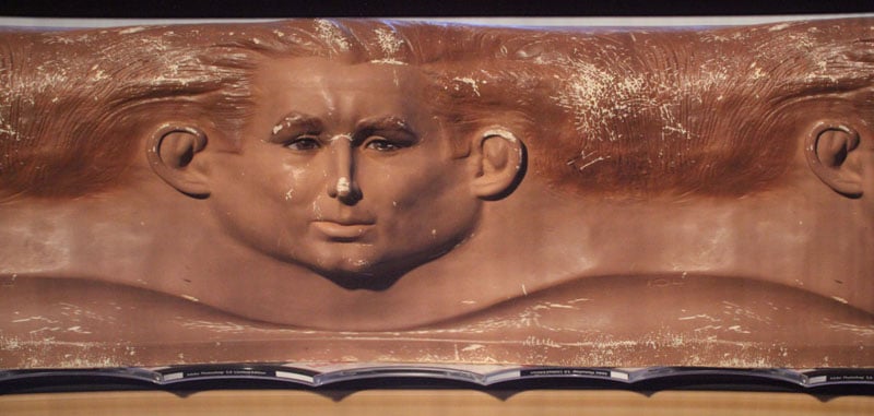
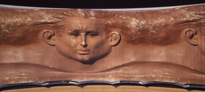
In addition to the distortion mentioned above you should note that the record can only display one particular subject diameter or circumference in the proper proportion. So irregular semi-cylindrical subjects (such as human heads) will not exhibit subject proportions correctly everywhere. After all, think about it: The process essentially flattens out an irregular surface. Much like it is impossible to flatten a sphere such as a globe of the Earth to a flat sheet so it is also not possible to reproduce all subject diameters exactly everywhere.
Note also that if the image of the slit is moving too quickly or too slowly vs. the rotation rate of the camera you will not reproduce the subject’s surface detail sharply in addition to the subject appearing to be stretched out or compressed.
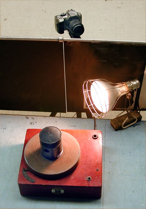
There are numerous applications for such photography starting with forensic applications (to lift images of fingerprints wrapped around a round object such as a pencil or bullet casings, or to compare markings on bullets to validate that they are identical or not, etc.) to showing wear patterns in engine pistons or cylinders, to display on a flat sheet of paper the decorations or graphics around a piece of pottery or a vase from antiquity, and others I can’t think of right now.

And beyond rollout or peripheral photography one can use a system such as this for all kinds of other applications such as making photofinish photographs of races, display the behavior of a bouncing ball, the stitching rate and motion of a sewing machine or similar subjects, oscillation rate of a pendulum, etc.
Of course, I must admit that this is an improvised and simplified version of the more expensive systems mentioned at the beginning but it serves as a low cost introduction to the technique (compare the price of a cardboard box to the price of a Better Light scanning back…)
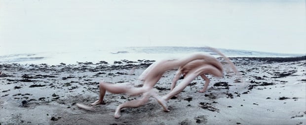
Finally making rollout portraits of people is great fun as well and it often leads to surprising results.

About the author: Andrew Davidhazy is a Professor at the Rochester Institute of Technology’s Imaging and Photographic Technology department. In addition to teaching technical, scientific, and industrial photography, he also covers special effects and techniques such as panoramic photography. You can find more of his work and projects on his RIT page. This article was also published here.